

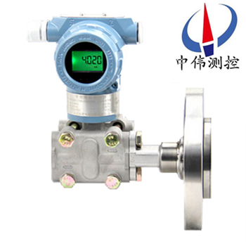
Single flange differential pressure transmitter
Description:
1, the structure:
Single flange level transmitter by differential pressure transmitter, capillary and belt of flange seal diaphragm.Seal diaphragm role is to prevent the pipe in the medium directly into the differential pressure transmitter, it is between the transmitter and by filling of liquid (usually use silicone oil) capillary connected, when diaphragm pressure to produce tiny deformation, deformation or frequency through capillary liquid is passed to the transmitter, the transmitter converts the output signal after processing.
2, appearance inspection:
A, flange check: check the flange connected to the equipment section of the seal are in good condition;Flange and capillary, capillary and itself if there is a connection part of the transmitter and capillary liquid leakage;Flange diaphragm deformation, damage, corrosion, scaling and other adverse conditions.
B, the transmitter inspection: check whether there is any damage, corrosion and other failure on transmitter shell, handle in time when problems found.
3, acceptance:
A, open the cover in the transmitter, check the sealing ring is damaged, if the damage to change in time;Check the circuit boards and other components are in good condition.
B, check the wiring of transmitter are in good condition.
C, disconnect the power supply, wire, insulation resistance checks, with a 500 v megohmmeter check transmitter terminals and shell, the insulation resistance between the resistance value should be greater than 20 m above.
4, single flange level transmitter to debug the check
In order to ensure that a measuring precision of the single flange level transmitter transmitter, cannot open capillary, so check to check with flange transmitter;Before installation, can use pneumatic analog signals and calibrate the HART com.
B, zero and span adjustment steps: zero and range of output, so that it is within the scope of permissible error.Continuous pressure, with the range of 0%, 25%, 50%, 75%, 150% of the pressure calibration, when pressure is stable after the record on the standard ammeter displays the current value and do return error checking.If calibration error exceeds permissible error range, should readjust the check.Adjusting method when operated by HART, see HART instructions accordingly.
4, installation:
A, far eastone flange installation:
High and low pressure on both sides of the flange should be installed correctly, can't put wrong;To reduce the influence of environment temperature difference, can be high and low voltage side of capillary bundle together, and fixed to prevent the wind and the influence of vibration and so on (super long section of the capillary volume in fixed together).Be careful not to damage the surface of the liquid membrane.Don't distort, extrusion capillary, don't put too much pressure to it.
B, the installation of transmitter ontology: use the installation bracket, the transmitter ontology is installed on the pipe diameter of 50 mm.Can be installed in horizontal pipe and the vertical piping installation.
5, note:
A, the four bolts fastening measuring capacitance room, connecting the capillary and let room part of the set screw must not loose, liquid sealed to prevent leaks, instrument damage.
B, wiring should avoid large capacity transformer, motor or power with power interference sources;Wiring should disconnect the power supply interface of dustproof plug;Thread department should undertake waterproof processing (waterproof processing is used when no hardening of silicone sealant series);To prevent interference, and other signal cable should avoid power cable through the same cable protection tube;For explosion-proof type instrument, in order to ensure the explosion-proof performance, must be in accordance with the relevant provisions of the wiring.
Eight, maintenance:
The following is our maintenance of flange transmitter is introduced.
1, occur during the winter freeze, when installed in the outdoor anti-freezing measures needed for transmitter, without pressure, fluid due to the icing volume expansion in the mouth, lead to the damage of sensors.
2, connection, cable through the waterproof connector (attachment) or round tube and screw down the sealing nut, such as in case of rain through the cable leakage into the transmitter inside the shell.
3, when measuring the pressure of the gas, apply pressure to open at the top of the process piping, flange level transmitter and also will be installed in the upper part of the process pipe so that the deposition of liquid pipelines of rapid injection to the process.
4, single flange level transmitter measuring steam or other high temperature medium, the need to connect with the buffer tube (coil) such as condenser, should not make the transmitter operating temperature more than limit.
5, pay attention to the pressure pipe of a sensor to install where small temperature fluctuations.
6, when measuring the liquid pressure, flange level transmitter installation location should avoid the impact of the fluid (water hammer), in order to avoid the sensor damage of overpressure.
7, when measuring the liquid pressure, pressure pipe side should be open in the process, in order to avoid precipitation product residue.
Eight, to prevent flange transmitter and corrosive or overheating medium contact, prevent the dross in intraductal deposition.
Nine, selection of code:
ZW3051LT | (work pressure 2.5 MPa) wei measurement and control of the () | ||||||||
code | Scale range KPa | ||||||||
3 | 0-1.3 ~ 7.5 | ||||||||
4 | 0-4-40 | ||||||||
5 | 0 to 40 ~ 200 | ||||||||
6 | 0-0.16-700 | ||||||||
code | The output | ||||||||
E | 4-20mA | ||||||||
S | Intelligent type (HART protocol) | ||||||||
code | Nominal diameter size (mm) | Insert tube length (mm) | High side diaphragm material | ||||||
A0 | (3), 80 | flat | 316LSST | ||||||
A2 | (3), 80 | 50 | 316LSST | ||||||
A4 | (3), 80 | 100 | 316LSST | ||||||
A6 | (3), 80 | 150 | 316LSST | ||||||
B0 | (4) 100 | flat | 316LSST | ||||||
B2 | (4) 100 | 50 | 316LSST | ||||||
B4 | (4) 100 | 100 | 316LSST | ||||||
B6 | (4) 100 | 150 | 316LSST | ||||||
C0 | (3), 80 | flat | Hartz C - 276 | ||||||
C2 | (3), 80 | 50 | Hartz C - 276 | ||||||
C4 | (3), 80 | 100 | Hartz C - 276 | ||||||
C6 | (3), 80 | 150 | Hartz C - 276 | ||||||
D0 | (4) 100 | flat | Hartz C - 276 | ||||||
D2 | (4) 100 | 50 | Hartz C - 276 | ||||||
D4 | (4) 100 | 100 | Hartz C - 276 | ||||||
D6 | (4) 100 | 150 | Hartz C - 276 | ||||||
E0 | (3), 80 | flat | tantalum | ||||||
F0 | (4) 100 | flat | tantalum | ||||||
code | Installation of flange | ||||||||
A | 3〞150lb | ||||||||
B | 4〞150lb | ||||||||
C | 3〞300lb | ||||||||
D | 4〞300lb | ||||||||
code | Junction structure materials | ||||||||
Flange and joint | Vent/drain valve | Isolation diaphragm | Pump the liquid | ||||||
22 | 316 stainless steel | 316 stainless steel | 316 stainless steel | Silicone oil | |||||
23 | 316 stainless steel | 316 stainless steel | Hartz alloy C | ||||||
24 | 316 stainless steel | 316 stainless steel | monel | ||||||
25 | 316 stainless steel | 316 stainless steel | tantalum | ||||||
33 | Hartz alloy C | Hartz alloy C | Hartz alloy C | ||||||
35 | Hartz alloy C | Hartz alloy C | tantalum | ||||||
code | options | ||||||||
M1 | 0-100% linear indicator | ||||||||
M2 | LED display table | ||||||||
M3 | LCD display table | ||||||||
B1 | Bend tubes of stents | ||||||||
B2 | Plate bending bracket | ||||||||
B3 | Pipe bracket with flat | ||||||||
D1 | The upper side discharge valve in the pressure chamber | ||||||||
D2 | Lateral release valve at the bottom of the pressure chamber | ||||||||
Don't note | 1/2 NPT taper pipe nipple | ||||||||
C2 | Jump nipple M20 x 1.5, with the back of the welding Ф 14 | ||||||||
d | Flameproof d Ⅱ BT4 | ||||||||
i | The Ann type ia Ⅱ CT6 | ||||||||
Browse:
