

Intelligent electric float liquid level transmitter
Intelligent electric float liquid level transmitter to adopt advanced technology of weighing sensor,…
Description:
Products overview:
ZW - TDZ seriesIntelligent electric float liquid level transmitterIs the introduction of foreign technology, design and manufacture of high performance and low cost products.Float liquid level gauge is in line with the HART protocol of intelligent liquid level instrument.Characterized by using microprocessor with HART communication circuit on the design, support the PC software of HART communication protocol or two-way communication 275 operator, and the output characteristics of liquid level measurement for linearization processing, measuring error compensation, the output signal delay, since the diagnosis function, etc., realize the intelligent digital processing, and with the traditional two wire 4 ~ 20 ma analog signals compatible.This series flameproof and intrinsically safe products, widely used in petroleum, chemical industry, metallurgy, electric power, food, papermaking, pharmaceutical and other industrial production process control testing system.
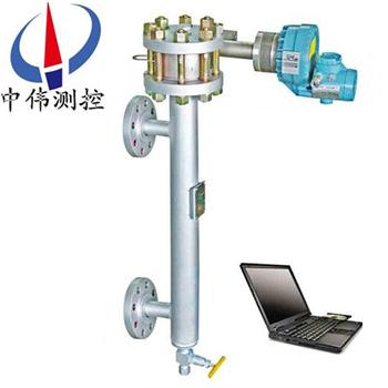
Second, the structure:
ZW - TDZ series intelligent electric float liquid level transmitter by detection, conversion and transmitter of three parts.Detection part by buoys, float chamber, connecting rod component parts;Part of the conversion is lever system, sensors, etc;Part of the transmitter is A/D, D/A conversion, microprocessor and signal output circuit and other parts.
Third, how it works:
ZW - TDZ series intelligent electric float liquid level transmitter is by means of Archimedes's principle and force balance principle and work.Is equal to the measured liquid level height buoy hanging next lever end, liquid level rises, buoy immersed in a liquid, and Archimedes upward buoyancy effect.
1, when the liquid level rises, float to lose weight, change bearing point leverage, measured by weighing sensor buoy the size of buoyancy, the liquid surface height can be.After the transformation, the output proportional to liquid level height 4 ~ 20 ma. DC standard signal.Far to the control room, realize remote liquid level display and process control.
2, the use of different calculation method, to measure the interface of two different medium height or certain proportion of medium.Transmitter indicator with 0 ~ 100%, and 0% is 4 ma, 100% for 20 ma.
3, because of the different medium density, will affect the size of the buoy buoyancy, therefore, with density and zero transmitter, adjust potentiometer, in order to adjust the output signal.
Four, the main features:
Use the hand held programmer and other equipment to the HART communication protocol on site and remote intelligent transmitter does the following:
1, read the process variables
Such as the original variable value, mA, percentage range, etc.
2, zero and range Settings
Operator to adjust by hand or use the transducer zero and full potentiometer to adjust.
3, read the diagnostic information
Diagnostic information are: parameter is set too high, too low;Range of measurement;4 ~ 20 ma beyond range, etc.
4, HART communication instructions
Use hand operator or other equipment and intelligent transmitter to communicate, can be read on the screen information such as the PV value, current value and percentage.Can use all HART instructions within the scope of implementation.
Five, the technical parameters:
Measuring range: 300 ~ 3000 mm (bigger range can be customized);
Plus or minus 0.5% FS precision: level measurement, the position plus or minus 1% FS.
Repeatability: plus or minus 0.25% or less FS.
Dead zones: plus or minus 0.2% or less FS.
Power supply: 12 ~ 30 VDC;
: the output signal: 4 ~ 20 madc;
Digital quantity: according to the HART or FOXCOM newsletter, FF fieldbus communication protocol;
Liquid crystal display: analog mA or liquid level, the position and the percentage of scope;
Load resistance: 700 Ω (24 VDC power supply);
Density range: 100 < rho < 2000 kg/m3;
Zui small density difference: 0.05 g/cm3;
Pressure of work: 2.5 ~ 32.0 MPa;
Medium temperature: 196 ~ + 400 ℃;
Ambient temperature: - 40 ~ + 70 ℃.
The influence of working conditions:
Power supply: when the voltage of the prescribed voltage zui changes between small value and zui, output variation + / - 0.2% or less FS.
Temperature effect: 0.1% / 10 ℃ or less;
The alarm current: when the liquid level is lower than the transmitter range when the lower limit of 10% or 10% above the transmitter range limit, fault alarm output current in the transmitter, according to the set of 3.8 22.8 mA mA or;
Protection grade: IP65 (NEMA 4 x);
Explosion-proof level: this Ann type: ExiaIICT1 ~ T4;
Flameproof: ExdIICT1 ~ T6.
Electrical interface: within 2 1/2-14 NPT thread;
Cable diameter: 6 ~ 12 mm,
The process connection:
Inside the bucket: use DIN or ANSI flange, flange size DN80 or 3 "above, smaller flange size when ordering, please consulting;
Buoy type: HG20592 ~ 20635-97 more than 3/4 "flange, other flange standards (GB, JB/T, HGJ, ANSI, DIN, etc.) when ordering user, please indicate;
Hot jacket: DN15 PN1.0 RF, when ordering, please indicate the other specifications;
Amplifier installed fission type accessories: installation components;
Cable length: 3 m/m/user to specify length;
Material: buoy: 304;316;
The clamping body: carbon steel;304;316;Hartz C alloy;
Clamping body jacket: 304;
Buoy: carbon steel;304;316;
Torque tube: 316 l;J1 Inconel 600 and 3, 3 j53, hartz C alloy;
Junction box: aluminum alloy.
Six, transducer calibration:
1, debugging, check carefully whether the machine installed correctly as required before wiring, buoy, let room and related torque tube components can not have medium leakage.
2, the output signal detection.When leaving the factory, the products are according to the order of calibration, the user after I receive my order, usually don't have to calibrate the measuring range.But because of the influence of vibration in the process of transportation or handling, putting-in-service proactively may find transducer zero when the corresponding changes have taken place, but the linear unaffected, so the instrument after installation to the scene, just put the zero calibration before put into use to + / - 0.50% (corresponding to the liquid level).
Transmitter at the scene hi-lo set according to pack after calibration.When the buoy let indoor liquid level change indicator reading change accordingly.
Analog output and parameters corresponding to the following:
Low setting: press 0% longer than 5 seconds,
Set the LRV as 4 ma
High setting: press 100% longer than 5 seconds
Set the URV as 20 ma
Damping Settings:
Display at the scene when the adjustable damping time, factory damping value is 8 seconds, can adjust between button 0-8 seconds.
Press 100% less than 3 seconds to display the current damping value, continue to hold 100% key gradually increase the damping, after being selected damping quickly press, 0% key confirmation, through the HART protocol calibration or FOXCOM calibration according to the related user guide.
Seven, debug method points to hang heavy method and water standard method of two kinds:
1, the hanging weight method:
Liquid level debugging:
Bring buoyancy calculation:
L buoy buoyancy: F1 = PI / 4 d. h. rho
L buoy heavy G and the difference between the buoyancy: F2 = G - F1
Type: D - buoy diameter (cm);
H - buoy length range (transmitter) (cm)
Rho - medium density (g/cm3)
Bring to fix level transmitter on the calibration on the shelf, and according to the figure 5 connection.
1) zero debugging ma (4)
On the tray into the buoy with heavy G such as heavy weight (including pallet), zero adjustment potentiometer, make the output of 4 ma.
(2) full debugging 20 ma)
With F2 in tray into the equivalent amount of weight (including pallet), adjusting range potentiometer, make the output of 20 ma.
According to (1), (2) two step, adjust a few times repeatedly, until satisfied.
2, debug interface:
Bring according to two kinds of medium density, respectively to calculate the weight density of buoyancy FQ and Fz
FQ = PI / 4, D2, h. rho Q
FZ = PI / 4 d. h. rho z
Type: D - (cm) H - buoy long buoy diameter (range) (cm)
Rho Q - light medium density (g/cm) rho z - heavy medium density (g/cm)
Bring calculated according to the FQ and FZ zero hung heavy weight weight fo hang heavy weight weight FM and full scale.
fo=G-FQ
fm=G-FZ
Type: G - weight buoy marked (sign)
1) zero debugging ma (4)
L on the tray into the same fo farmar (including pallet), equivalent to the value of the zero potentiometer, transfer to 4 ma
If l rho Q light medium density is higher than when placing order, provide the density of 0.1 g/cm3, it is possible tuning out 4 ma phenomenon.At this point, according to zero potentiometer will adjust the direction of the original 10 turns in the opposite direction, make the potentiometer is basic in the middle position, to adjust the density of the potentiometer, make the output of 4 ma.Then zero adjustment potentiometer, make the output of 4 ma accurate values.
2) full debugging
On the tray in the FM equivalent weight, adjustable range potentiometer, make the output of 20 ma.
2, water proof method:
1. The liquid level debugging
Bring about medium density 1 g/cm3 or less (water) :
According to the measured medium density and range,
Full range of water level height h (mm) :
H = h. rho
Type of H - buoy the length (span) mm:
Rho - measured medium density, g/cm3
(1) zero debugging
Net buoy indoor water, zero adjustment potentiometer, make the output of 4 ma.
(2) full debugging
Open the inlet valve, added water to the buoy indoor, make higher water equal to h, immediately shut off the water valve, adjusting range potentiometer, make the output of 20 ma.
According to (1), (2) two step, adjust a few times repeatedly, until satisfied.
Bring about medium density > 1 g/cm3 (water) :
When the density is greater than the density of water measured medium, will take any point within the range as a full pilot (cap) is set.Debugging before, should first calculate the corresponding water level and point by point within the range of the current value.
For example: the range of 1500 mm, the medium to be measured density is 1.1 g/cm3, take 1300 mm for full (limit) the pilot, is:
Corresponding water level should be: h = 1300 * 1.1 = 1430 (mm)
Which corresponds to the current should be followed: Ⅰ = 4 x 16 + 1300/1500 = 17.87 (mA)
After the calculation, debug method is as follows:
1, zero debugging
Net buoy indoor water, zero adjustment potentiometer, transfer to 4 ma.:
2, full debugging
Full debugging is at level 1430 mm for the range potentiometer, make the output of 17.87 mA, repeated several times, until satisfied.
3, interface debugging
Bring about two kinds of medium density 1 g/cm3 or less (water)
L, according to two different kinds of medium density respectively calculate the zero level corresponding h0 stated (mm) and full of water level height h (mm)
H0 rho Q = H
Hm = H rho z
Type of H - range (buoy long mm)
Rho Q - light medium density (g/cm)
Rho z - heavy medium density (g/cm)
After l calculated h0 and hm, the scale line with buoy underside height as a benchmark, draw the h0 and hm, respectively, on the scale of markup
4, zero debugging:
L to buoy indoor infuse water, the water level is equal to the h0, close the inlet valve, zero adjustment potentiometer, make the output of 4 ma
If l rho Q is higher than the density of light medium when placing order, provided by the density of 0.1 g/cm or more, it may be transferred out 4 ma phenomenon.At this point, the zero adjustment potentiometer in the direction of around 10 turns in the opposite direction, the potentiometer is basic in the middle position, and adjust the density of the potentiometer, the output is 4 ma, then again zero adjustment potentiometer, make the output of 4 ma accurate value, 2) full debugging
To buoy the indoor infuse water, making water level equal to hm, close the inlet valve, adjustable range potentiometer, make the output of 20 ma.
According to the above (1), (2) two step, adjust a few times repeatedly, until satisfied.
Bring heavy medium density > 1 g/cm3 (water)
Full adjustment, preferable than zero the debug level h0 any point as a full range of pilot, specific methods can refer to water level debugging "medium density > 1 g/cm3 (water)" debug method.
5, commissioning method of measuring the proportion of:
Debug method and measuring interface basic same, just calculate the buoyancy is poor, by the same proportion of medium in zui daiwa zui small to calculate the two points.
6, the linearity of the debug method:
Good linearity modulated before they go out in the transmitter, the user generally do not need to check, just according to the parameters set zero and full (upper and lower limit).If user want to check linearity, according to the following formula to calculate weight, check any point within the range of linearity.
1) when measuring liquid level
Farmar, any position (x %) = G - PI / 4 d, x %, h. rho
2) any position when measuring interface heavy weights (x %) = G - PI / 4 d. H (x % Δ rho + rho (Q)
3) when the proportion of measurement
Calculation formula and the liquid level measurement formula are basically the same, just according to the proportion of different weight value calculation.
All kinds of: G - buoy weight (G)
H - buoy length (cm)
Rho - medium density (g/cm)
Δ rho - two kinds of medium density difference, Δ rho = rho z - rho Q
Rho z - heavy medium density (g/cm)
Rho Q - light medium density (g/cm)
X % - the percentage of span length (buoy)
Eight, zero migration issues when measuring interface:
Measuring interface, buoy the upper parts are immersed in the medium, therefore, will produce certain buoyancy, the buoyancy is a constant, additional current produced by it is also a science, it raises the good range without any influence, just lead to zero point slightly higher than the modulated good zero value (ma) 4, this additional current value is very small, if the measurement accuracy is not high, just don't have to zero migration, if the measuring accuracy is higher, need to attach the current migration.
Here are two kinds of migration methods, for reference:
1, will buoy indoor all full of light medium (note: must make the buoy upper parts all immersed in the light, medium, and adjust the zero potentiometer, make the output current 4 ma.
2, can be observed in any of the interface, the zero adjustment potentiometer, make the output current and the interface point corresponding to the current value.The above two kinds of debugging method, the user can choose according to actual condition, other methods may be adopted.But please note that no matter what method is adopted to improve the migration, can only be zero adjustment potentiometer.
Nine, installation considerations:
1, out of the box, to avoid excessive shock and vibration
2, the end of the first lever clamp screw drive, tie the buoy hang, will limit clamp installed, then the table head protection support screw is put into use.
3, should be solid and reliable, float chamber must ensure that the vertical, in order to prevent the buoy collided with buoy interior wall.
4, in the process, with a strong vibration or shock to prevent transducer, especially for buoy hook shall not substantially swing or pull, in order to avoid damage to the sensor, reduce the precision of instrument.
5, for easy to condensate, easy to crystallization, easy to precipitate and larger viscosity should be chosen with insulation jacket measured medium type, the site should be equipped with steam pipeline.
6, on the spot, using the method of hanging weight transmitter access device after debugging, as long as the parameters are calculated accurately in the debug, is in the range of current variation (20 ma - 4 ma ma = 16) will not change.In use, if do not tally with the actual measured value, the output current value may be due to vibration in the buoy assembly process, caused by vertical degree of zero change.At this point, can be adjusted at any measurements on zero potentiometer, made the current are in conformity with that point measured value can be zero (this process can only adjust potentiometer).
Ten, use notice:
1, explosion-proof products, before installation shall check the explosive-proof grade of transmitter, temperature classes and associated equipment is matched with the environment.
2, when debugging and maintenance, shall not change the circuit parameters and structure, may not change the specification, type and parameters of the components
3, transmission cables and transducer introduced device in connection to flexible protection tube, transmitter terminal connection should add insulation casing
4, good transmitter enclosure must be grounded
5 zui, working environment temperature shall not exceed 60 ℃;Electric components and wires zui shall not exceed 35 ℃ high temperature
6, manufactured products, did TuHong transmitter key parts of the mark, mark, please don't twist, lest affect transmitter performance.If necessary, please contact with the company, timely and properly handle
7, transmitter connection
This safety type wiring diagram as shown in figure 7.When wiring, should try to avoid the influence of the external electromagnetic interference, cable distribution parameters should be controlled within the specified value.
8, the installation and maintenance, safety barrier shall comply with the safety gate operating instructions.
9, explosion-proof transmitter system installation operation and maintenance, should strictly abide by the explosive dangerous location electrical safety regulations of the People's Republic of China.
10, transmitter deposit, should be stored in ventilated dry inside storeroom, and should not contain the transmitter has corrosion substance or gas.
Browse:
On A:Intelligent electric buoy level (world) transmitter
Next:Intelligent electric float level gauge
