Address:No. 4-4 East West Road, Jinhu County Industrial Concentration Zone, Huaian City, Jiangsu Province
Tel:0517-86918678
Fax:0517-86918679
Email:zhongweick@163.com
Post Encoding:211600
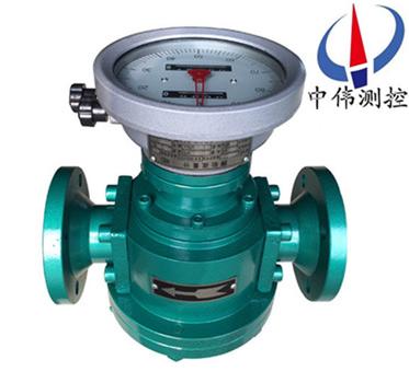
ZW-LL series <strong> turbine flowmeter</strong> is a volume flow measuring instrument, …
Description:
Productoverview:
ZW-LL series turbine flowmeter is a volume flow measuring instrument, measuring part adopts stainless steel material, strong corrosion resistance, can be used for aqueous corrosion of crude oil or other corrosive medium flow measurement.This scene shows the cumulative flow and flow meter can be equipped with remote output interface, the other with the photoelectric converter output electric pulse signal or analog signal, matched with a flow meter for remote measurement, display and control.
The utility model is characterized in that a metering chamber in the meter casing, the metering chamber has a pair or two pairs of tangent waist wheel rotation.In the outside of the casing and two meter coaxial search round a set of transmission gears meshing with each other, they make the two round the waist can be linked with each other.
Can the cumulative flow, and is equipped with remote output interface, the other with the photoelectric converter output pulse signal or analog signals, and supporting the flow totalizer, remote measurement display and control.
ZW-LL series turbine flowmeter is mainly composed of a metering chamber, a sealing coupler is composed of three parts and a counter.The scene indicates the cumulative flow and instantaneous flow, with the transmitter and the flow controller, can realize remote measurement and control.Widely used in petroleum, chemical, electric power, metallurgy, transportation, food processing, medicine, defense, trade and other departments accurate measurement of oil and oil products, chemical solution and other fluid.
Two, work principle:
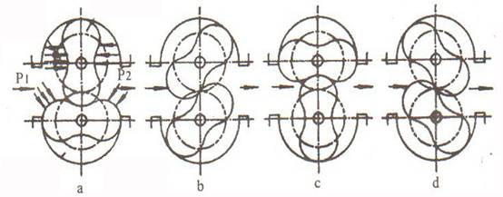
ZW-LL series of flowmeter is when the measured liquid flows through the metering chamber, in the import and export of the formation of differential pressure flowmeter, this pressure waist wheel driven by rotation.At the same time through fixed at the waist on the axle of the driving gear, the two round of continuous rotation of the waist.With the rotation of the waist wheel, the metering chamber is discharged continuously through the liquid flowmeter.The amount of each liquid flow through the metering chamber volume is four times, the sealing mechanism through the coupling, reducer, reducer rotating number is transferred to the counter, the counter is indicating liquid instantaneous flow and cumulative flow.Install the transmitter in the counter mechanism that the sender of the waist belt.With the display meter or computer system can realize remote (quantitative, cumulative and instantaneous automatic measurement and control function).Use display instrument Classification Manual see.
Three, application of measurement:
ZW-LL, can be used for pure crude oil, heavy oil flow measurement of high viscosity liquid;
ZW-LL-D can be used to prevent sand sand flow measurement of crude oil, heavy oil and other high viscosity fluid;
Contact type flowmeter and ZW-LL-F stainless steel medium stainless steel material manufacturing, has strong corrosion resistance, can be used for flow measurement of corrosive liquid, especially for the chemical industry;
ZW-LY-C light oil type is especially suitable for light oil, diesel oil flow measurement of low viscosity fluid.
Four, main features:
1, high measurement accuracy, the basic error is generally up to plus or minus 0.2% to plus or minus 0.5%, special requirements up to plus or minus 0.1%, flow characteristics generally not affected by the flow state, nor by the Reynolds number size limit.
2, can be used for high viscosity liquid flow measurement
3, a wide range of measurement, the typical flow range of 5:1 to 10:1
4, the cumulative amount of fluid type wheel counter, without external energy, the use of instant noodles counter cumulative flow double display, one of which can be reset to zero, the convenience of users in the case of continuous measurement.
5, the measurement between components without contact, no wear, long service life.
6, large caliber flowmeter and the rotor, reduce running noise and vibration meter.
1, flow meter should be installed before the filter, the meter with the direction of arrow.
2, when the measured liquid containing gas, flow meter should be installed before the gas separator.
3, whether the pipeline is vertical or horizontal installation, but the waist wheel flowmeter installation into a horizontal position (i.e. dial should be perpendicular to the ground).
4, the correct installation of flowmeter in the case, if it is not easy to see the readings, the counter rotating 180 degrees or 90 degrees can be.
5, the throttle valve should be installed in the meter inlet opening and closing valve is installed at the outlet, the use of open or close the valve to start slowly, do not suddenly open valve.
6, prohibited the use of steam flowmeter by line sweep.
7, in the continuous use of departments, need to add a bypass pipeline flowmeter.
Before the installation of 8, flow meter, pipeline flushing, flushing the pipe (alternative meter position) prevent the welding slag and other debris into the meter.
9, check the water meter is composed of cast iron, cast steel.
10, when using the size of the flow meter shall not exceed the technical requirements.The flowmeter work on Zui flow 70~80% was better.
11, if the measured liquid is corrosive, need to use stainless steel flowmeter, if corrosive, need to use 0Crl8Ni12MO2Ti material flow meter.
Seven, installation notes:
1, before installation shall not open the inlet flow, the outlet seal two;
2, when the pipe is installed on the device more, should be put on after the installation of flow meter;
3, where conditions permit, the pipeline must be high pressure purge before installation;
4, the installation should at the interface of iron pins, careful removal of burr;
In front of the 5 meter must be installed, filter, filter media measurement; measurement of liquid, if containing gas, optional getter device flowmeter, ensure the measuring precision of flowmeter;
6, installation modes, horizontal vertical installation can be installed vertically progress under the lower upper is not affected, but the meter shall not be reversed, anti loaded, opposite directions, waist wheel reversal, because the rotation between different gap design will damage the waist wheel;
7, on the lower straight pipe section, but must set aside to install filtering device enough distance;
8, waist wheel rotation is by fluid pressure as the driving force, viscous medium when the measurement is too high, affect the measuring precision of flowmeter;
To avoid the above points, the measurement precision can achieve better flowmeter.
Eight, technical performance:
project
Model
Nominal diameter (mm)
Nominal pressure
(Mpa)
The measured liquid temperature (c)
Flow range (M? /h)
% accuracy
The installation form
ZSmall flow
ZLarge flow
ZW-LL-8
Eight
0~1.6
0~2.5
0~4.0
0~6.4
Zero point two five
Two point five
Zero point two
Zero point five
Horizontal and vertical
ZW-LL-15
Fifteen
Zero point two five
Two point five
Zero point two
Zero point five
Horizontal and vertical
ZW-LY-20
Twenty
-20~+60
Zero point two five
Two point five
Zero point two
Zero point five
Horizontal and vertical
ZW-LL-25
Twenty-five
Zero point six
Six
Zero point two
Zero point five
Horizontal and vertical
ZW-LL-40
Forty
One point six
Sixteen
Zero point two
Zero point five
Horizontal and vertical
ZW-LL-50
Fifty
-20~+120
Two point five
Twenty-five
Zero point two
Zero point five
Horizontal and vertical
ZW-LL-80
Eighty
Six
Sixty
Zero point two
Zero point five
Horizontal and vertical
ZW-LL-100
One hundred
Ten
One hundred
Zero point two
Zero point five
Horizontal and vertical
ZW-LL-150
One hundred and fifty
-20~+350
Twenty-five
Two hundred and fifty
Zero point two
Zero point five
Horizontal and vertical
ZW-LL-200
Two hundred
Forty
Four hundred
Zero point two
Zero point five
Horizontal and vertical
ZW-LL-250
Two hundred and fifty
A heat sink
Sixty
Six hundred
Zero point two
Zero point five
Horizontal and vertical
ZW-LL-300
Three hundred
One hundred
One thousand
Zero point two
Zero point five
Horizontal and vertical
Pressure loss: the measured liquid viscosity is less than 30mpa.s, the pressure loss is less than 0.05Mpa.
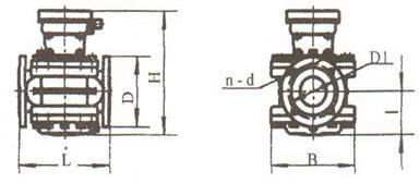
Nine, appearance and installation size:
Table 1, cast iron type size:
Model
L
H
I
B
D
D1
N-D
ZW-LL15.06
One hundred and sixty
Two hundred and thirty-eight
Fifty-two
100*100
G11/4
ZW-LL20.06
One hundred and sixty
Two hundred and thirty-eight
Fifty-two
100*100
Ninety
Sixty-five
ZW-LL25.06
One hundred and eighty
Two hundred and sixty
Sixty-eight
120*120
G1/
ZW-LL40.1
Two hundred and forty
Two hundred and ninety
Eighty-eight
One hundred and seventy
One hundred and fifty
One hundred and ten
4-17.52
ZW-LL50.1
Two hundred and sixty-five
Three hundred and five
Ninety-seven
One hundred and ninety
One hundred and sixty-five
One hundred and twenty-five
4-C17.52
ZW-LL80.1
Two hundred and sixty-five
Three hundred and forty
One hundred and twenty-two
Two hundred and forty-six
Two hundred
One hundred and sixty
8-17.52
ZW-LL80II.1
Two hundred and sixty-five
Four hundred and seventy
One hundred and sixty-four
Two hundred and forty-six
Two hundred
One hundred and sixty
8-18
ZW-LL100.1
Five hundred and fifteen
Four hundred and twenty-five
One hundred and sixty-four
Three hundred and five
Two hundred and twenty
One hundred and eighty
8-18
ZW-LL150.1
Five hundred and sixty
Five hundred and fifty
Two hundred and twenty-five
Four hundred and fifty-five
Two hundred and eighty-five
Two hundred and forty
8-22
Table 2, casting dimension:
Model
L
H
I
B
D
D1
N-D
ZW-LL25.3
One hundred and eighty
Two hundred and sixty
Sixty-eight
120*120
G11/4
ZW-LL40.4
Three hundred
Two hundred and ninety
Eighty-eight
One hundred and seventy
One hundred and fifty
One hundred and ten
4-18
ZW-LL50.4
Three hundred and sixty
Three hundred and fifteen
One hundred and three
Two hundred and seventy-six
One hundred and sixty-five
One hundred and twenty-five
4-18
ZW-LL80.4
Three hundred and sixty
Three hundred and forty-eight
One hundred and twenty-eight
Two hundred and fifty-four
Two hundred
One hundred and sixty
4-18
ZW-LL100.3
Five hundred and forty
Four hundred and thirty-five
One hundred and seventy-four
Three hundred and thirty
Two hundred and thirty-five
One hundred and ninety
4-22
ZW-LL150.3
Five hundred and sixty
Five hundred and fifty-two
Two hundred and twenty-seven
Four hundred and fifty-five
Three hundred
Two hundred and fifty
4-26
Cast aluminum shape and dimensions of the same type of cast iron.