

Intelligent PID controller
The intelligent PID controller has been developed for nearly 70 years. It has become one of the main…
Description:
Products overview:
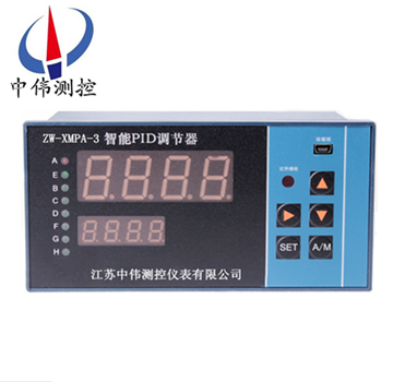
ZW - XMPA seriesIntelligent PID regulatorNo adjustable parts, without any auxiliary function module, all the parameters setting, function mode selection, the accuracy of the calibration are analog input and output by the keys on the instrument panel, in order to correct the rational use of the instrument, give full play to the functions of the instrument, please read this manual carefully before using the subsequent parts.Instrument before delivery according to your order has been set up correctly, if you want to change the corresponding set parameters, also must be familiar with industrial control site of the technical personnel on the basis of fully understanding the performance of this instrument to operate.
Second, the applications:
ZW - XMPA seriesIntelligent PID regulatorFor small and medium-sized technology device of temperature, pressure and other parameters of single loop control.Can be applied to metallurgy, petroleum, chemical industry, building materials, paper making, food, medicine, heat treatment and water treatment and other industrial field.
Three, the main functions:
Can choose 1, 20 multiple input signal (measured input signal prescribing and small signal can be removed).
2, process capacity, given value, the control quantity, quantity of valve position feedback, such as multiple display.Of the given value and the measured value shows that addition and subtraction can be performed.
3, choice of control PID adjust the positive and negative effect.
4, can be independently set the upper and lower limit value of PID regulator.
5, the PID parameters self-tuning or P parameters self-tuning independently.
6, boot boot manually or automatically and manual output values can be preset.
7, hand automatic two-way undisturbed switching and manual instructions and output.
8 the given value, input switch SB function control and displacement.
9, two or three analog output.
10, instrument were six open output, also can be set up one of the switch to the other two switch monitors the condition of the quantity has the choice of implementation with a quieter time intelligent sound and light alarm function.
11, remote of EM1, EM2 control.
12, 50 hz synchronized bidirectional thyristor zero fill control algorithm to achieve the optimization of each orthodox wave control, to avoid the high power load higher harmonic pollution to power network.
13, intermittent PID regulator of the instrument can be built for the user a bidirectional thyristor direct control ac 2 km below 40 single output impedance load or 3 groups trigger below 500 a bidirectional thyristor sync signal.
14, 8 group given value SP1 and P, I, D parameters of storage and call.
15, remote control switch quantity control regulator output for PID regulating mode or maintaining state, two-way switch without disturbances.
16, given value and the PID parameters online Settings without disturbances.
17, remote control of switch quantity control regulator input for PID regulating mode or tracking status, two-way switch without disturbances.
18, instrument internal PID adjustment or a type of control at the same time, you can define one or two relay to realize each channel 100 hours timing accuracy of 10 to 5 dual channel timer function.
19, break, break, break after I can fault control output, also can be blocked with valve position feedback or bolt (1 ~ 5, 4 ~ 20 ma) fault control output.
Four, the technical parameters:
1, the accuracy of measurement: plus or minus 0.5% FS + 1 d + / - 0.2% FS + 1 d
2, analog input impedance: current signal: 50 or less Ω;A voltage signal: 500 k or Ω
3, analog output impedance: current signal: 0 ~ 10 ma acuity 1.5 k Ω;4 ~ 20 ma Ω 750 or higher
The voltage signal: 0 ~ 5 v, 1 ~ 5 v output impedance Ω 1 or less
4, switch output, ac 220 v, 3 a resistance (load)
5, manual/automatic state output: automatic status to break;Manual status to pass
6, the parameters of the set when the power is keeping time: 20 years or more
7, insulation resistance, voltage 1500 v, 1 minute
8, insulation resistance: 50 m Ω above
9, working environment requirement: temperature: 0 ~ 50 ℃, relative humidity 85% or less, no corrosion aerosols, no vibration.
Five, the display shows:
1, double screen
A, digital tube on the measurement, display input signals, enter the parameters set mode display setting parameters of the prompt.
B, discharge digital tube display controller given value or control quantity or percentage of the percentage of the amount of valve position feedback (please specify when ordering.Manual state in the form of percentage according to manual control output.Enter the parameters set mode display setting parameters.
Article 2, double screen + single simulation
A, digital tube display input measurement on the measurement signal, into the parameters set mode display setting parameters of the prompt.
B, discharge digital tube display controller given value or control quantity or percentage of the percentage of the amount of valve position feedback (please specify when ordering.Manual when displayed in percentage manual control output.Enter the parameters set mode display setting parameters.
C, simulation shows that the percentage of the amount of valve position feedback or PID control volume (please specify when ordering)
Article 3, single + double simulation
A, digital tube display input signal measured or regulator measurement displayed in given value or as A percentage or in the form of percentage display control valve position feedback signal, use the add button to switch the display mode.Manual state in the form of percentage according to manual control output.Way into the parameter Settings when the display setting parameters of prompt and set parameters.
Article B, left simulation in the form of percentage according to the main input signal measurement.
C, right simulation in the form of percentage display controller given value or valve position feedback quantity or amount of PID control.
Article 4, double screen + double simulation
A, digital tube display input measurement on the measurement signal, into the parameters set mode display setting parameters of the prompt.
B, discharge digital tube display controller given value or control quantity or percentage of the percentage of the amount of valve position feedback (please specify when ordering.Manual state in the form of percentage according to manual control output.Enter the parameters set mode display setting parameters.
C, left simulation in the form of percentage according to the main input signal measurement.
D, displayed in right article simulated as a percentage measure or PID control valve position feedback.
5, three screen display
A, digital tube display input measurement on the measurement signal, into the parameters set mode display setting parameters of the prompt.
B, out digital tube display the percentage of the amount of valve position feedback.Manual state in the form of percentage according to manual control output.Enter the parameters set mode display setting parameters.
C, the percentage of the discharge amount of digital tube display control.
Article 6, single digital display + three simulation
A, digital tube display measurement on the input measurement signal, control or trace quantity or amount of A given value, can use the key selection display.Set the alternate display setting parameters of prompt and set parameters.
B, the first article 24 line simulation in the form of percentage according to the main input signal measurement.
C, the second article 24 simulation in the form of percentage showed a given value.
D, the third article 24 line simulation display control in the form of percentage.
7, indicator light
A, LED - A is intermittent PID control or SP1 alarm status indicator light
B, LED - E for SP2 alarm status indicator
C, LED - B for SP3 alarm status indicator
D, LED - C for automatic lamp or SP4 alarm status indicator light
E, leds - G for manual indicator
F, - D to discharge digital tube LED display to control the volume status indicators
J, -f for discharge digital tube LED display for process status indicators
K, leds - H for a given state indicator
Six, selection table:
| ZW-XMPA | —— | Said Ming | ||
| Design sequence | 3 | In the intelligent PID controller (wei measurement and control) | ||
| Display mode | 1 | Double screen | ||
| 2 | Three screen display | |||
| 3 | Double screen + single beam | |||
| 4 | Double screen + double beams | |||
| 5 | Single + double beams | |||
| 6 | Single + three beams | |||
| Input mode | 1 | With a thermocouple (E, K, S, B, J, T, R, N) | ||
| 2 | With thermal resistance (Pt100, Cu50, Cu100, BA1, BA2, G) | |||
| 3 | With direct current (0 ~ 10 ma, 4 ~ 20 ma) | |||
| 4 | With a dc voltage (0 ~ 5 v, 1 ~ 5 v, 0 to 20 ma, 0 ~ 75 ma, 0 ~ 200 ma), | |||
| 5 | With remote transmission pressure resistance and linear resistance value (0 ~ 400 Ω) | |||
| 6 | All with 1 ~ 5 types, user can change at any time including any kind of input type | |||
| 7 | Frequency input (0 ~ 10 KHZ) | |||
| 8 | Special input (such as root, cut of small signal, order please indicate) | |||
| Control the output and the adjustment way | The continuous PID way | 1 | PID4 ~ 20 ma output (reaction) | |
| 2 | PID0 ~ 10 ma output (reaction) | |||
| 3 | PID0 ~ 5 v output (reaction) | |||
| 4 | PID1 ~ 5 v output (reaction) | |||
| 5 | PID0 ~ 10 v output (reaction) | |||
| 6 | One positive effect (1 ~ 5, order indicate) | |||
| 7 | One 1 ~ 6 + relay indicating the amount and type of relay (order) | |||
| Intermittent PID way | 1 | Built-in SCR (two-way within 41 a, 2 kw) output | ||
| 2 | Built-in SCR (two-way 41 a, 2 kw) output (add 2 or 3 relay, order indicate) | |||
| 3 | External SCR silicon silicon (single or double) | |||
| 4 | Silicon silicon thyristor converter (single or double) (add 2 or 3 relay, order indicate) | |||
| 5 | Three phase zero interpolation method is used thyristor trigger (trigger current more than 500 ma) | |||
| 6 | Three-phase thyristor zero trigger add 1 or 2 relay (order) indicated | |||
| 7 | SSR solid state relay output (12 v) plus two relay alarm (users with SSR technology parameters) | |||
| Additional features (note) | 0 | No additional features | ||
| 1 | Output limit, lower limit control | |||
| 2 | There are boot manual function | |||
| 3 | EM1 function | |||
| 4 | EM2 function | |||
| 5 | SB function | |||
| 6 | Self-tuning function | |||
| 7 | 8 groups of PID parameter selection | |||
| 8 | The ratio control: SP = x outside A given + B | |||
| 9 | Display and valve position feedback tracking control (the default input 4-20 ma) or order | |||
| Overall dimensions | H | Horizontal type 160 x 80 | Opening 152 x 76 | |
| V | Vertical 80 x 160 | Opening 76 x 152 | ||
| F | The way to 96 by 96 | Opening 92 x 92 | ||
| Q | The way to 72 by 72 | Opening 68 x 68 | ||
| Analog output | A | There is no analog output | ||
| B | Analog 0 ~ 10 ma | |||
| C | Analog output 4 ~ 20 ma | |||
| D | Analog 0 ~ 5 v | |||
| E | Analog output 1 ~ 5 v | |||
| F | Special signal analog output | |||
| G | Feedback the output (the default input) | |||
| Timing function | S | Default is no timing function | ||
| With the function of timing | ||||
| For the 24 v dc power supply | P | Default is no 24 v dc power supply output | ||
| With 24 v dc output power (to do two wire transducer power) | ||||
| Communication interface | T | The default is not to bring a communication interface | ||
| With RS485 and RS232 communication interface | ||||
| Power supply | K W | Default is 220 v AC | ||
| Switching power supply of 85 ~ 260 vac | ||||
| Switching power supply 18 to 36 VDC or 18 ~ 36 vac | ||||
Note: additional optional a variety of functions, its serial number add note when you order it, 4, 5, 6 can only choose a kind of additive and its function.
After-sales service commitment:
1, our company sold by wei measurement and control products quality problems within twelve months, responsible for free maintenance.
2, the warranty period, any quality problems such as the products of our company, my company is responsible for free repair or replacement.
3, the warranty period, such as user improper use, damaged products, my company is responsible for the maintenance, charge damage parts cost.
4, after the warranty period appear quality problem, my company is responsible for the maintenance, charge damage parts cost.
5, such as user need to my company site services, to users in the province I company service personnel to reach the site within 12 hours, fujian association of foreign languages and user reach the site within 48 hours.
Browse:
