

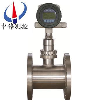
Digital display target type flowmeter
Digital display target flowmeter in 60 s application in the industrial flow measurement, is mainly u…
Description:
I. product overview
ZW - BSL series digital display target flowmeter using capacitive force sensor is the new product key core to realize high precision, high stability, completely changed the target flowmeter has a strain type temperature drift is big, poor ability to resist overload (shock), there are some shortcomings such as static seal, not only played a target flowmeter the original technical advantages, at the same time is comparable to those of volumetric flowmeter measurement accuracy, together with its unique anti-interference, impurity resistance, in addition to substitute for conventional flow measurement can measure flow problems, Especially in small flow, high viscosity, easy to coagulate and block, high temperature, low temperature, strong corrosion, strong vibration and other flow measurement difficult conditions have good adaptability.
Ii. Structure and working principle
1, structure,
Zw-bsl series digital display target flowmeter is mainly composed of measuring tube (shell), new type sensor (including choke element), integrating display and output part. Suitable sensors must be selected according to different media and working conditions. Therefore, accurate measurement objects and parameters provided by users and appropriate sensors selected by manufacturers are the key to accurate measurement of products.
2. Working principle
When medium in the measurement of pipe flow, because of its kinetic energy and target plate pressure difference, and produce on the target plate force, make the target board of trace amounts of displacement, the force is proportional to the square of the velocity with the media, the size of the target plate force of the target bar transfer, make the sensor elastomer produces trace changes, thereby breaking patches of capacitance bridge balance. Generate voltage signal corresponding to the force of flow on the target plate: influenced by the fluid flow characteristics, the flow is proportional to the square of the voltage generated by the bridge. Its mathematical expression is as follows:
CdA rho/V2 / F = 2
Where: the force (kg) exerted on F flow arrester
The drag coefficient of the Cd object
A axial projection area (mm2) of flow arrester on measuring tube
Rho medium density on condition (kg/m3)
Average velocity of V medium in measuring tube (m/s)
The force F received by the choke (target) is transmitted to the sensor through the rigidly connected transmitter (measuring rod), and the sensor generates voltage signal output: V=KF
Where: V -- voltage (mV) output of the sensor, K -- proportionality constant, F -- force (kg) on the choke (target),
After the voltage signal is preamplified, AD converted and processed by computer, the corresponding instantaneous flow and cumulative total amount can be obtained.
Iii. Application:
Zw-bsl series digital display target flowmeter can replace the flow measurement problems that can be measured by conventional flow, especially in the flow measurement difficulties such as high viscosity, dirty medium, easy to coagulation and blockage, high temperature, low temperature, strong corrosion, etc. It has good adaptability. Widely used in petroleum, chemical, energy, food, environmental protection, water conservancy and other fields. From the effect after its use, it has a very broad applicability, that is:
1, suitable for all kinds of pipe diameter: from 15-2000 mm Φ Φ to bigger.
2, suitable for high and low temperature medium: from - 196 ℃ ~ + 450 ℃.
3, suitable for high pressure conditions: from 0 to 42Mpa (surface pressure).
Iv. Main features:
1. It can accurately measure the flow of liquid, gas, steam, viscous medium and various fluid media under various conditions of normal temperature, high temperature and low temperature.
2. Extremely sensitive, able to measure ultra-small flow rate, and its low flow rate is 0.08m/s.
3, no moving parts, safe and reliable use.
4, accurate measurement, high precision, the total measurement can be up to 0.2%.
5, wide measuring range, zui large measuring range up to 1:30.
6, good repeatability, generally 0.1 ~ 0.08%, rapid measurement.
7, small pressure loss, only standard hole plate 1/2 delta P or so.
8. Dry calibration method can be adopted, i.e.
9. The measurement flow range can be changed by changing the target plate according to actual needs.
10, can read the value online, and can send the message.
11. Easy installation and easy maintenance.
V. technical parameters:
1. Medium under test: liquid; Gas; steam
2. Nominal diameter pipeline type: 15~300mm clamping type: 15~600mm plug-in type: 100~2000mm
3. Nominal pressure: 0.6~42MPa
4, medium temperature: - 20 ℃ ~ 70 ℃ (room temperature). - 196 ℃ ~ + 450 ℃ (high and low temperature type)
5. Accuracy: 0.2%, 0.5%, 1.0%, 1.5%, 2.5%
6. Range: 1:3, 1:5, 1:10, 1:10 (gas), 1:10 (steam)
7. Compensation type: temperature compensation; Pressure compensation
8. Repeatability: 0.1%~0.08%
9. Power supply: 3.6v lithium battery is built in; External power supply 24VDC; 220VAC (for split digital tube display only)
10. Output form: display the reading value on site; 4~20mA (two-wire system); Pulse; 0 ~ 10 v
RS232/RS485 (optional)
11. Measuring tube material: carbon steel; 304; 316 l; It is also available upon request
12. Explosion-proof mark: safety safety (ExiallCT4) flame-proof (ExiallBT4)
13. Protection level: IP65; IP67
Note: the flange specification of flowmeter is in accordance with GB/T9115.1~9115.4-2000 series standards. The pipe type can produce DN6, DN8, DN10 and other small diameter flowmeters according to the needs of customers.
Vi. Installation instructions:
1. The flow meters of normal temperature, low temperature and high temperature shall be installed horizontally, vertically or inversely depending on different working conditions (subject to the factory check sheet);
2. When the working temperature of the medium is above +300, the user shall adopt thermal insulation measures to prevent the meter head from being damaged by thermal radiation (the working temperature of the meter head is -30 to +70). Similarly, the anti-freezing measures shall be taken for the medium with the working temperature below -100;
3. In order to ensure the accurate measurement of the flow meter, the front and rear straight pipe sections shall be set;
4. To ensure that the flow meter does not affect the system during inspection and replacement, bypass valve (3) and cut-off valve (1, 2) should be set as far as possible;
5. Vertical installation can be adopted due to process requirements. The flow direction of the medium under test can be from bottom to top or from top to bottom.
6. The diameter of the flow meter should be the same as that of the connected pipe to reduce flow interference and measurement error.
7, the meter housing must be reliable grounding, if there is no grounding conditions should be explained to the factory.
Vii. Fault handling:
With the failure self-test program, users can find out part of the reasons through the display screen:
1. When the measured medium velocity in the pipeline is zero, the instantaneous flow value indicated by the flowmeter is not zero. The main reasons for this phenomenon are as follows:
A. The level of the flowmeter is inconsistent before and after installation, so that the horizontal axial component of the target and the target rod is inclined, resulting in instantaneous flow;
B. the flow meter runs for a long time, and the internal stress release of the sensor changes slightly;
C. serious overload causes zero drift during installation or operation;
The above three methods can be referred to the procedures and methods for the zeroing of the flow meter.
D. Poor grounding of the meter housing;
Processing method: user regrounding.
E. The target, target bar and measuring tool are stuck by debris;
Treatment: close the valve before and after the flowmeter, loosen the connecting bolt between the excessive part of the flowmeter and the measuring pipe with the tool, gently shake the transition part or take it out, and restore it as it is after cleaning the sundries.
2. The display value of the flowmeter increases abnormally in the working process, and the main reasons for this phenomenon are as follows:
A. there are filamentous and banded sundries hanging on the target and target rod;
Disposal method: refer to the disposal method of sundries.
B. Under the condition of high engender engender, the target and the target bar have serious engender engender, which increases the projected area of the target plate along the axis of the measuring tube. That is to say, the annular flow area between the target and the measuring tube decreases.
Method of treatment: remove the transition parts, remove the object with tool to remove the target, the shaft and the wall inside the tube.
3. Due to the large measurement error, there are many reasons for this phenomenon. The main reasons for zui are as follows:
A. During installation, the relative concentricity between the flow meter and the connecting pipe is relatively large dislocation, and the sealing gasket is not concentric, thus forming the throttling resistance, which greatly affects the flow state of the measured medium;
Processing method: adjust installation status.
B. The front and rear straight pipe sections of the flowmeter are too short, and elbow, valve and other components that greatly interfere with the measured media flow state are directly installed in front of the flowmeter;
Treatment: install or calibrate the flow meter according to the instructions.
C. bypass pipe leakage;
Treatment: check and replace the bypass line.
D. There are banded sundries on the target, which increases the target's stress;
Disposal method: refer to the previous disposal method of sundries.
4. The flow meter has no indication or signal, and the main reasons are as follows:
Browse:
