

I. product overview
Zw-lz series metal tube float meter is a variable area flowmeter based on float position measurement. Modular concept design is adopted as Modular design, which is amajaas Modular concept design, because of its small volume, small pressure loss, large range ratio (10:1), easy installation and maintenance, etc., it is widely applied to flow measurement and process control of small flow, low flow rate and various harsh medium conditions under complex and bad environment in various industries. For different user needs, different occasions, there are a variety of measurement forms for users to choose; According to the output form, there are local indication type, remote transmission type and control alarm type; according to the output form, there are local indication type, remote transmission type and control alarm type; According to the classification of explosion-proof requirements, it can be divided into three types: ordinary type, intrinsic safety type and isolated explosion-proof type. The design and production also consider the user process flow requirements, there are vertical installation, top in bottom out installation, side in side out installation, bottom in side out installation, thread connection, horizontal installation and other installation options.
Ii. Structure and working principle
1. Structure
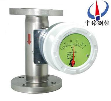
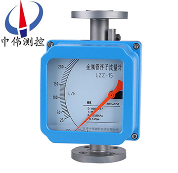
Zw-lz series metal tube float meter is mainly composed of three parts:
A. indicator (intelligent indicator, local indicator);
B. float;
C. conical measuring chamber.
2. Working principle:
Bottom-up measured medium by the conical float to the top and bottom side of the differential pressure measurement of a tube formed upward force, when the float upward force is greater than the baptism by float weight in the fluid, float up, clearance area increase, immediately drop the gaps in the fluid flow, float up and down the differential pressure is reduced, on the float upward force as well as to reduce, until the upward force equal to the float weight immersed in the fluid, the float is stable at a certain level. The height of float position corresponds to the size of the measured medium flow. Magnetic steel is built into the float. When the float moves up and down with the medium, the magnetic field changes with the float.
A. For the local type, the rotating magnetic steel in the local indicator is coupled with the magnetic steel in the float to rotate and drive the pointer at the same time, indicating the flow rate at this time through the dial.
B. For intelligent type, A solid state magnetic sensor in the intelligent indicator converts the change of magnetic field into electrical signal, which is processed by A/D conversion, microprocessor, D/A output and LCD liquid crystal display to display the size and cumulative flow.
Iii. Conversion indicator:
The converter actually converts the height of the float in the cone tube to the scale of the corresponding volume flow. From the output signal to: there are local display type and remote signal output type:
1. Local display type: the following magnetic steel in the local indicator is coupled with the magnetic steel in the float to rotate, and the electric pointer indicates the current flow through the dial.
Type 2, intelligent remote transmission, by intelligent indicator of follow-up magnetic steel and the float inside the magnetic coupling, and the rotation, sensing magnetic steel and pointer at the same time, through A magnetic sensor to magnetic field changes into electrical signal, after the A/D conversion, digital filtering, microprocessor processing, D/A output, LCD liquid crystal display (LCD), to show the size of the instantaneous flow and cumulative flow.
Iv. Application:
Zw-lz series metal tube float flowmeters are widely used in petroleum, chemical industry, power generation, pharmacy, food, water treatment, etc. Complex, harsh environmental conditions, and various media conditions in the flow measurement process.
V. main features:
1, all-metal structure design, strong, simple, high pressure resistance, high temperature resistance, corrosion resistance, long service life;
2. Short stroke, total height 250mm, easy installation;
3. Mechanical pointer indicates instantaneous flow on site, and LCD displays instantaneous flow and cumulative flow;
4, intelligent indicator, using the new zui signal acquisition and processing chip, modular design, no magnetic hysteresis;
5, with data recovery, data backup, power off protection and error self-diagnosis function;
HART indicator, two-wire 24VDC power supply, 4-20ma standard current signal output superposition HART protocol;
7. Parameter configuration and field adjustment can be carried out through HART communication hand controller;
8. Connect with PC serial port, and calibrate the instrument on site through Windows program;
9, can be used in flammable, explosive dangerous occasions;
10, vertical, horizontal, top in and bottom out, bottom in and side out, side in and side out and other installation forms, flange or thread connection.
Vi. Technical parameters
1, the measuring range: water 2.5 ~ 100000 l/h (20 ℃)
2. Range ratio: 10:1
3. Accuracy level: 1.0, 1.5, 2.5
4. Working pressure: PN4.0MPazui for DN15, DN25 and DN50 is 10.0mpa, and PN1.6MPazui for DN80 and DN100 is 6.4mpa
5, medium temperature: - 40 ℃ ~ 300 ℃
6. Medium viscosity: DN15: vertical <5mPa·s (F15.1 ~ F15.3)
Vertical <30mPa·s (F15.4 ~ F15.8)
DN25: eta < 250 mpa, s
DN50 ~ DN150: vertical <300mPa·s
7, environment temperature, liquid crystal type: - 40 ℃ ~ 85 ℃
A pointer type: - 40 ℃ ~ 120 ℃
8. Connection form: flange (according to the standard DIN2501 or manufactured according to the flange standard provided by the user)
9. Instrument height: 250mm
10. Cable interface: M20*1.5
11. Power supply: 24VDC two-wire system 4-20ma or 85-265vac 50/60hz (far transmission)
12, alarm output: the upper or lower limit instantaneous flow alarm relay output (contact capacity zui big 5 a - 250 vac) or open collector output (100 ma zui large internal impedance Ω 100-30 VDC).
13, pulse output: cumulative pulse output, every 10 seconds every pulse (alternating) or every 50 milliseconds a pulse.
14. Liquid crystal display: double-row liquid crystal display, displaying instantaneous flow and cumulative flow.
15. Intrinsically safe and explosion-proof: Exia II CT4.
16. Measuring tube material: 316 stainless steel (normal type) or lined with ptfe (anticorrosive type).
Vii. Description of structure classification
1. High-temperature structure (type G)
High temperature structural type (G type) is used for medium temperature is too high or too low and need to take heat preservation and heat insulation measures for the measuring pipe medium flow measurement. The high-temperature type structure increases the distance between the measuring tube and the indicator to increase the heat dissipation and increase the heat insulation material thickness to ensure that the indicator works within the allowable environmental temperature range. Type G was selected. Can measure the temperature of 80 ℃ to + 300 ℃ medium flow.
2. Structure with damper device (type Z)
Dampers are designed to measure the flow of media when the flowmeter inlet flow (pressure) is unstable, especially for gases.
3. Jacket structure (type T)
The jacket type structure is used for flow measurement of media requiring heat or cooling (such as high viscosity and easy crystallization). By heating or cooling medium in the jacket, the fluid with low boiling point and low freezing point is not vaporized or crystallized.
Hg20594-97 DN15 PN1.6 flanges shall be used for the inlet and outlet connection of the heat tracing medium. The connection of other flanges can be marked with the manufacturer. The pressure grade of the jacket is 1.6mpa.
4. High-pressure structure (y-type)
High pressure type structure is used to measure the flow rate of the medium under test whose pressure is higher than the standard pressure level. The high-pressure type structure is shown below. Currently FFM64 series zui can reach 32MPa high pressure. In addition, the high-voltage flow meter can be provided with a built-in magnetic filter, and the installation height is 350mm. FA, FB and FC zui have a high pressure of 10MPa.
Viii. The following steps shall be followed during installation:
1. Before installation to process pipeline, remove all installation and check whether there is any transportation damage;
2. To prevent the rubber band with fixed pointer in the indicator during transportation, open the left cover of the indicator and remove it gently before wiring without changing the position of the pointer;
3, open the right cover of the indicator, cable through the cable into the device, according to the rotation Angle transmitter wiring wiring diagram, tighten the nut, cable fixed, and then tighten the fastening screw on the left and right cover, make the indicator waterproof and dustproof;
4. The upper and lower pipelines of the meter shall be the same as the diameter of the meter, and the connecting flange or thread shall be matched with the flange and thread of the meter. The length of the upstream straight pipe segment of the meter shall be 5 times of the nominal diameter of the meter, and the length of the downstream straight pipe segment h2 shall be no less than 250mm;
5. Since the measuring mechanism of the instrument adopts magnetic transmission, in order to ensure the performance of the float flowmeter, no ferromagnetic substances are allowed at least 100mm around the installation of the sensor;
6, before the installation of the instrument, the process pipeline should be purged to prevent the ferromagnetic substances in the pipeline from adhering to the instrument, affecting the performance of the instrument, or even damaging the instrument.
7. The instrument for measuring gas is calibrated under special pressure. If the gas is directly discharged into the atmosphere at the outlet of the instrument, pressure drop will be generated at the float and data distortion will be caused. If this is the case, a valve should be installed at the outlet of the meter so that the required flow value can be set. When the calibration pressure is maintained on the float, the gas will expand at the valve.
8, the instrument installation form is divided into vertical installation and horizontal installation, if it is a vertical installation form, should ensure that the straightness of the instrument is better than 1%; If it is a horizontal installation should ensure that the level of the instrument is better than 1%;
9, the instrument installed in the pipeline should not be subjected to the role of stress, the outlet and entrance of the instrument should be appropriate pipe support, can make the instrument in the zui small stress state;
10. When the product is connected with the computer for calibration and other operations, it must be carried out in a safe place.
Ix. Troubleshooting methods:
1. Check the SU alarm setting size.
2. Check the deviation and set the d value not to be too large.
3. Is the logic function correct in the FUN function? HA-A means upper bound positive logic. LA -a means lower bound positive logic
4, circuit board fault, replace the circuit board.
5. If the LCD bar code indicates correctly and no output action is made, check whether the external power supply and the negative pole of the external power supply are connected to the negative pole of the meter power supply.
If there is jitter in use, you can determine which range of jitter is based on the range of jitter. Dither is divided into slight dither, moderate dither and violent dither.
1. Slight dithering: generally caused by medium fluctuation. It can be overcome by increasing the damping.
2. Moderate jitter: generally caused by medium flow state. For gas generally due to unstable medium operating pressure. The instrument gas damping can be overcome or increased by means of voltage or current stabilizer.
3, violent jitter: mainly due to the medium pulsation, pressure instability or the user's gas operation state of the pressure, temperature, flow and the actual state of the instrument is inconsistent, there is a big difference caused by the meter over range.
As long as the use of the correct method, usually pay attention to maintenance, you can ensure its normal use.
X. product maintenance:
1. During the long-term use, ferromagnetic impurities will inevitably be adsorbed on the float in the pipeline, which will cause the float to get stuck or affect the measurement accuracy. If magnetic filters are installed, they should also be cleaned regularly.
2, the meter indicator is equipped with electronic components, the meter wiring or disassembly of the housing, to screw tight, must ensure the sealing of the housing, prevent impurities, water or other substances into, but also to ensure the reliable grounding of the meter housing.
3. After the instrument is installed, pay attention to:
Open the valve in order to avoid the formation of pressure impact so that the float impact limit device, resulting in the damage of the instrument, must slowly open the valve!
Gas gauges are equipped with gas dampers, zui to reduce the float oscillation to a large extent; To ensure the stability of the float, a throttle valve can be installed at the outlet of the meter.
4, for the remote instrument, first of all to ensure the correct wiring of the instrument, can be energized; For dangerous occasions, explosion-proof type must be selected, and according to the explosion-proof requirements for installation and use.
11. Precautions for installation.
1. After unpacking the flowmeter, remove the filling material. The flowmeter should be installed vertically on the pipe without vibration. The center line of the flowmeter and the vertical Angle should not exceed 5 °.
2. The newly installed pipeline shall be flushed clean before the installation of the metal tube float flowmeter. If the measured medium contains particle impurities or bubbles, the filter device or exhaust port shall be installed on the upstream of the flowmeter. If the medium under test is pulsating flow, a buffer device of appropriate size, such as a pressure stabilizing tank, should be set downstream to eliminate pulsating flow.
3. Globe valve and bypass valve shall be installed on and downstream of the flowmeter for convenience of checking zero point of the flowmeter and disassembly, maintenance and debugging.
4. After the primary meter is installed as required, shut off the upper and lower cut-off valves of the flowmeter, and then check the connection between the primary meter and the secondary meter. If there is no error, the instantaneous flow shall be displayed as zero if the secondary meter is turned on. If the normal use, should first open the upstream valve is fully open, with metal tube float meter downstream regulator valve from small to large slow regulation flow, the instantaneous flow should change. When stopped, the upstream valve should be closed, and then close the downstream regulator.
