

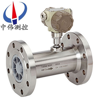
Pulse output gas turbine flowmeter
ZW - LWQ - N seriesPulse output gas turbine flowmeterIs learned the flow meter at home and abroad ad…
Description:
ZW - LWQ - N seriesPulse output gas turbine flowmeterIs learned the flow meter at home and abroad advanced technology optimization design, integrated the theory of gas mechanics, fluid mechanics, electromagnetism and the self-developed set temperature, pressure, flow sensor, and in the integration of intelligent flow totalizer.especially for a new generation of high precision, high reliability of gas precision measuring instrument, has a good performance of low pressure and high pressure measurement, sensitivity to low fluid perturbation, is widely used in natural gas, coal gas, liquefied gas and light hydrocarbon gas such as gas measurement.
This kind of turbine flow product itself does not have the display function, only the transmission of traffic signal in the form of a pulse far out.Instrument low price, high integration, small size, and especially suitable for the secondary display, such as PLC, DCS computer control system.
Second, the working principle:
ZW - LWQ - N seriesThe principle of pulse output of gas turbine flowmeter is a fluid flowing through the sensor shell, as a result of the impeller blade and flow to a certain point of view, the impact of fluid blade with rotational torque, to overcome the friction torque and fluid resistance, blade rotation speed stability after the moment balance, under certain conditions, the speed is proportional to the velocity of flow, because the blade has a magnetic conductivity, it is in the signal detector (composed of * magnetic steel and coil) magnetic field, rotating blade cutting lines, periodically changing coil magnetic flux, so that the coil ends induction electrical pulse signal, the signal after amplifier amplification plastic, form a certain amplitude of continuous rectangular pulse wave, can be spread far to display instrument, show the instantaneous flow and cumulative amount of fluid.Within the scope of a certain flow, pulse frequency f and flows through the sensor of fluid is proportional to the instantaneous flow rate Q, flow equation is: Q = 3600 x f/k;Type:
F - pulse frequency (Hz);
K - the instrument coefficient of sensor 1 / m3, given by the check list.If [1 / L] as the unit
Q - fluid transient flow (working conditions) (m3 / h),
3600 - conversion factor.
Coefficient of each sensor of the instrument in the calibration certificate will be completed by the manufacturer, set into the display instrument of form a complete set of k value, can show the instantaneous flow and cumulative total.
Applications:
ZW - LWQ - N seriesPulse output gas turbine flow meter with high precision, good repeatability, simple structure, less moving parts, high pressure resistance, wide measuring range, small volume, light weight, small pressure loss, easy maintenance, etc, used for measuring low viscosity the volume of a gas in a closed pipe flow and total amount.In petroleum, chemical industry, metallurgy, urban gas network industries has wide use value.
Four, the main features:
1, wide measuring range, the lower velocity of less than 0.5 m/s, small pressure loss, the impeller impact resistant ability.
2, has the high resistance to electromagnetic interference and vibration resistance, self-lubricating bearing adopts full sealing isolation protection, performance reliable working life is long.
3, USES the advanced ultra low power single chip microcomputer technology, the whole machine function is strong, low power consumption, superior performance.With nonlinear compensation function of intelligent traffic monitor precision.Accuracy is better than that of plus or minus 0.02%.
4, meter coefficient can be set up by the key online and can be displayed on the LCD screen, LCD screen clear intuitive, high reliability.
5, block the EEPROM for cumulative flow, instrument coefficient of power-fail protection.To protect more than 10 years.
6, can be in the measured gas pressure compensation under stable state of stress.
Five, the technical parameters:
1, the nominal diameter: pipeline: DN4 DN200 ~;
2, plug-in: DN100 ~ DN2000;
3, precision grade: pipeline: + / - 0.5 level, plus or minus 1.0 on the Richter scale;
4, plug-in: 1.5 mm, 2.5 mm;
5, environmental temperature: - 20 ℃ to 50 ℃;
6, medium temperature: liquid measurement: - 20 ℃ ~ 120 ℃;
7, measuring gas: - 20 ℃ ~ 80 ℃;
8, atmospheric pressure: 86 kpa to 106 kpa.
9, nominal pressure: 1.6 Mpa, 2.5 Mpa, 6.4 Mpa, 25 Mpa;
10, explosion-proof level: ExdIIBT4;
11, connection mode: threaded connection, flange clamp outfit, flange connection, plug, etc;
12, straight pipe required: gas: a straight pipe upstream should be 10 or more dn, downstream straight pipe should be 5 or more dn.
13, liquid: straight pipe upstream should be 20 or more dn, downstream straight pipe should be 5 or more dn.
14, plug-in: straight pipe upstream should be 20 or more DS, downstream straight pipe should be 7 or higher DS (DS for pipeline measured diameter);
15, display mode:
(1) far eastone show: pulse output, the output current (match display instrument);
(2) the scene showed that eight LCD display cumulative flow, unit (m3);
Four transient flow, LCD display unit (m3 / h), battery, frequency, flow velocity;
(3) the temperature and pressure compensation type:
A, according to standard criteria for instantaneous flow and cumulative flow;
B, show the current pressure, temperature, battery voltage;
16, output functions:
(1)Pulse output, p - p values determined by power supply;
(2)4 ~ 20 ma two wire output current;
(3)Unit volume pulse output and the original pulse sensor output;
(4)With RS485 communication interface;
17, power supply:
(1)DC5~24V;
(2)Standard 3 v lithium battery installed on the instrument internal can use eight consecutive years;
(3)Temperature pressure compensation type 3 v lithium battery installed within the instrument can be continuous use of more than 4 years;
18, transmission distance: sensors to display distance up to 500 m.
Six, method of use:
1, after users to install good flowmeter, unscrew the back cover, plug in the battery power supply full screen (digital, Chinese characters), about 8 seconds
After the bell, can work normally.Replace the battery, you remove the power plug of the battery, change new battery can be back to work.Instrument coefficient does not change at this time.
2, 3, coefficient of double row liquid crystal display, load method
A. open the front cover, press to the right and F key at the same time, the instrument enter into the state of load, ranked first at this time
Words show 1, said at this time can be set * point meter coefficient.Four can be set up after the corresponding points on the sensor output pulse frequency value of the instrument coefficient of discharge can be set to eight point value.
B. first high flashing, press the up key, the bit to add 1 to the required value, press the shift key, blinking moves to the right, and then use the up button to choose the bit number...When flashing after displacement to a, according to the key, to put this parameter.Instrument coefficient of format for XXXXXX. XX
C. check after press the F key, can enter the next point meter coefficient setting, the setting method, the above format.
D. set up after the three coefficients at the same time press the press the right F, the instrument enter into the state of work, show on the four instantaneous flow, discharge display eight total flow.
E. in working status, press the F key, accumulative total can be reset.
Note: using three instrument coefficient of flow sensor nonlinear correction requires the user to know flow sensor and some corresponding meter coefficient (frequency) how much is respectively, namely the F1 - K1, F2 - K2, F3 - K3.
Set the parameter, after check, at the same time press the press the right F is back to work status, display on the four instantaneous flow, discharge display eight total flow.In working status, press the F key, the total amount can be reset.
Seven, installation reasons may lead to the problem:
1, the length of straight pipe upstream or downstream is insufficient;
2, instrument measuring pipe diameter and pipe diameter deviation;
3, install different heart, gasket convex tube;
4, instrument going backward;
5, detecting element is covered by impurities;
6, reduce the detection sensitivity, small leakage flow meter;
7, pipeline leak (installed in underground pipeline, for example, small leakage was found), valve leakage, by-pass valve leakage cause cumulative flow smaller (total);
8, there are two phase flow, pulsating flow influence the accurate measurement.
Eight, must be pay attention to the points:
1, requires clean measured medium, low viscosity, corrosion resistance is small, do not contain impurities, in order to reduce the wear of bearing.If the liquid to be measured a grudge or containing gas, the flowmeter before venting device.In order to avoid damage of impurity in the fluid into the transmitter devious, and in order to prevent turbine stuck, add filters when necessary.
2, the installation of the flowmeter should avoid vibration, avoid magnetic field and thermal radiation.
3, medium density and viscosity changes have an impact on flow value, should be revised if necessary.
Nine, structure and installation method:
1, instrument installation using thread connection and clamp type;
2, liquid flow direction when installation should be direction of arrow and indicating flow sensor shell, and a straight pipe upstream should be 6 D, or downstream straight pipe should be 5 D or higher measured pipeline measured diameter (D).
3, sensors should be far away from the external magnetic field, such as can't be avoided, necessary measures should be taken;
4, in order to not affect the normal delivery of the liquid, maintenance should be straight section on opposite sides of the sensor installation outside the by-pass pipe;
5, sensors, outdoor installation time, please prepare amplifier plug waterproof processing;
6, sensor and display instrument connection, should according to the power of the amplifier to choose connection mode, as shown in the relevant specification.
Ten, installation site:
1, the installation site should comply with the environmental temperature at 25 ~ 55 ℃ scope, humidity < 80% RH;
2, well ventilated, avoid sun and rain;
3, avoid in piping vibration or the place of stress;
4, avoid easily affected by the strong thermal radiation and radioactive places;
5, must avoid the outside strong electromagnetic field disturbance to the detection signal.If unavoidable, should be set on the amplifier of the flowmeter (sensor) shield and other measures to eliminate interference;
6, in the places where requires explosion-proof, and isolation amplifier should be adopted;
7, the installation position should consider ease of installation, operation, maintenance.
Eleven, installation requirements:
1, before installation, pipeline purging, and in case of residual iron affect the normal operation of flowmeter.
2, before the installation, the use of tiny air blows the turbine, the turbine can flexible rotation, no random noise, count rotation is normal, uninterrupted card lag phenomenon, the flowmeter can be used to install.
3, in the middle of the flange and pipe flanges to add sealing washer.
4, before the gas meter shall be equipped with filters, temperament is dirtier occasions should add oil filter, before you place an order, can order to me at the same time, it is strictly prohibited to filter and flowmeter directly connected.
5, gas turbine flowmeter in the installation shall be added as of before and after the valve.
6, flange joint pipe Canon there should be no protrusions.
7, when installation, it is strictly prohibited in the import and export directly to where the flange welding, so as not to burn out flowmeter internal parts.
8, shall be installed in easy maintenance, strong electromagnetic interference and mechanical vibration and thermal radiation effects.
9, unfavorable use frequent interruptions in the flow, and have strong pulsation flow or pressure pulsation of the occasion.
10 and outdoor installation, should be the upper cover, to prevent rain water immersion and strong sunlight affect the service life of the meter.
11, can be horizontal or vertical installation, the fluid flow direction should be consistent with the direction of the logo on the shell, should guarantee the upstream of the flow meter is not less than 10 dn straight pipe, after the table is not less than 5 dn straight pipe.
12, in order not to affect the normal fluid transportation, it is suggested that according to the figure 2 by-pass pipe installation, must close the by-pass pipe valve when normal use.
Twelve, method of use:
1, after users to install good flowmeter, unscrew the back cover, plug in the battery power supply full screen (digital, Chinese characters), about 8 seconds
After the bell, can work normally.Replace the battery, you remove the power plug of the battery, change new battery can be back to work.Instrument coefficient does not change at this time.
2, 3, coefficient of double row liquid crystal display, load method
A. open the front cover, press to the right and F key at the same time, the instrument enter into the state of load, ranked first at this time
Words show 1, said at this time can be set * point meter coefficient.Four can be set up after the corresponding points on the sensor output pulse frequency value of the instrument coefficient of discharge can be set to eight point value.
B. first zui high flashing, press the up key, the bit to add 1 to the required value, press the shift key, blinking moves to the right, and then use the up button to choose the bit number...When flashing after one in the displacement to zui, according to the key, to put this parameter.Instrument coefficient of format for XXXXXX. XX
C. check after press the F key, can enter the next point meter coefficient setting, the setting method, the above format.
D. set up after the three coefficients at the same time press the press the right F, the instrument enter into the state of work, show on the four instantaneous flow, discharge display eight total flow.
E. in working status, press the F key, accumulative total can be reset.
Note: using three instrument coefficient of flow sensor nonlinear correction requires the user to know flow sensor and some corresponding meter coefficient (frequency) how much is respectively, namely the F1 - K1, F2 - K2, F3 - K3.
Set the parameter, after check, at the same time press the press the right F is back to work status, display on the four instantaneous flow, discharge display eight total flow.In working status, press the F key, the total amount can be reset.
13, the use of notice:
1, in the low pressure table z pressure leak detection: 1.0 Mpa, or less temperature pressure compensation type leakage pressure no more than three times the upper limit value of the pressure sensor.High pressure casing according to 1.2 times the rated flow pressure leak detection.
2, after installation leak test and installation shall comply with the following provisions:
A close vent valve and the inlet valve first.
B slightly open vent valve, and then slowly open the inlet valve, make the table start slowly, then slowly open the vent valve, make the reach normal operation state, to prevent sudden start, damage to the core.
C at the time of stopping air, need to close the vent valve, then close the inlet valve, each time you start all should abide by the rules.
After 3, install and use, not to touch the bolt, screw, nut fasteners, such as to avoid danger such as leakage, damage.
4, flow meter movement (temperament clean) should be once every six months for cleaning maintenance;(temperament is dirtier) should be cleaning maintenance once a month.
5, if the movement after breakdown maintenance, to be put into use, the need to press z pressure seal test first.And note within the movement precision instrument transformer oil or oil.
14, parameter table:
Instrument model | ZW-LWQ-N | ZW-LWQ-A | ZW-LWQ-B | ZW-LWQ-C | ZW-LWQ-D |
Signal output | pulse | 4-20mA | There is no | 4-20mA | Optional 4-20 ma/pulse |
Power supply | +24VDC±15% | +24VDC±15% | The lithium battery | 24VDC±15% | 24 VDC plus or minus 15% + lithium battery |
Precision grade | 2.5 ~ 1.5 on the Richter scale are unlikely | 1.5 ~ 1.0 on the Richter scale are unlikely | 1.5 ~ 1.0 on the Richter scale are unlikely | ||
Measuring range | The standard range | Standard range or extension | Standard range or extension | ||
display | There is no | There are | There are | ||
Temperature, pressure compensation | There is no | There is no | There are | ||
Communication interface | There is no | There is no | RS485 | ||
Real time record | There is no | There is no | There are | ||
Instrument material | Aluminum alloy or stainless steel | Aluminum alloy or stainless steel | Aluminum alloy or stainless steel | ||
Explosion-proof grade | ExdIIBT6 or ExiaIICT4 | ExdIIBT6 or ExiaIICT4 | ExdIIBT6 or ExiaIICT4 | ||
Protection grade | IP65 | IP65 | IP65 | ||
The machine power consumption | < 1W | < 1W | < 1W | ||
Instrument drift diameter | DN25~DN300 | DN25~DN300 | DN25~DN300 | ||
installation | Flange installation | Flange installation | Flange installation | ||
Medium temperature | - 20 ℃ ~ 80 ℃ | - 20 ℃ ~ 80 ℃ | - 20 ℃ ~ 80 ℃ | ||
The environment temperature | - 30 ℃ ~ 60 ℃ | - 30 ℃ ~ 60 ℃ | - 30 ℃ ~ 60 ℃ | ||
15, measurement range and pressure rating:
Nominal diameter | model | The standard range | Extended range | Stress levels | High pressure rating | installation |
DN20 | ZW-LWQ-20 | 2.2-25 | 4-40 | 1.6 | 2.5, 4.0 | The flange |
DN25 | ZW-LWQ-25 | 2.2-25 | 4-40 | 1.6 | 2.5, 4.0 | Flange (thread) |
DN32 | ZW-LWQ-32 | 5-50 | 6-60 | 1.6 | 2.5, 4.0 | The flange |
DN40 | ZW-LWQ-40 | 5-50 | 6-60 | 1.6 | 2.5, 4.0 | Flange (thread) |
DN50 | ZW-LWQ-50 | 6-65 | 5-70. | 1.6 | 2.5, 4.0 | The flange |
ZW-LWQ-50 | 10-100. | 8-100. | ||||
DN65 | ZW-LWQ-65 | 15-200. | 10-200. | 1.6 | 2.5, 4.0 | The flange |
DN80 | ZW-LWQ-80 | 13-250. | 10-160. | 1.6 | 2.5, 4.0 | The flange |
ZW-LWQ-80 | 20-400. | The flange | ||||
DN100 | ZW-LWQ-100 | 20-400. | 13-250. | 1.6 | 2.5 | The flange |
ZW-LWQ-100 | 32-650. | The flange | ||||
DN125 | ZW-LWQ-125 | 25-700. | 20-800. | 1.6 | 2.5 | The flange |
DN150 | ZW-LWQ-150 | 32-650. | 80-1600. | 1.6 | 2.5 | The flange |
ZW-LWQ-150 | 50-1000. | The flange | ||||
DN200 | ZW-LWQ-200 | 80-1600. | 50-1000. | 1.6 | ... | The flange |
ZW-LWQ-200 | 130-2500. | The flange | ||||
DN250 | ZW-LWQ-250 | 130-2500. | 80-1600. | 1.6 | ... | The flange |
ZW-LWQ-250 | 200-4000. | The flange | ||||
DN300 | ZW-LWQ-300 | 200-4000. | 130-2500. | 1.6 | ... | The flange |
320-6500. | 1.6 |
16, selection of coding:
type No. | said Ming | ||||
ZW-LWQ- | - | -□ | /□ | /□ | |
type | N | In the pulse output type gas turbine flowmeter (wei measurement and control) | |||
Meter diameter | 25A/B/C | 25mm | |||
40A/B | 40 mm | ||||
50A/B | 50 mm | ||||
80 | 80 mm | ||||
100 | 100 mm | ||||
150 | 150 mm | ||||
200 | 200 mm | ||||
250 | 250 mm | ||||
300 | 300 mm | ||||
Sensor material | N | Basic material, high quality aluminum alloy.(pressure:1.0MPa) | |||
S | Stainless steel material.(high pressure anti-corrosion type) | ||||
Special structure | A | Oxygen is special structure (deoiling defatted processing) | |||
B | Special structure design (high velocity) compressed air | ||||
For example, the model is: the ZW - LWQ - N - 25 - A - A pulse output type gas turbine flowmeter, said:
Meter diameter is 25 mm, display and output pulse output, measurement accuracy is 1.0%;The turbine type pulse is measured normal flow rangeGas turbine flowmeter。
In the 17th and designing order selection guidelines:
1, instrument selection, as far as possible not to use the work flow in the lower limit value, so the meter diameter should be as small as possible, in order to obtain a larger flow rate and flow range.
2, the flowmeter should be used in the technical parameters of medium pressure and temperature range.Don't deliberately choose the high pressure level and ultra-high temperature instrument, should be selected according to the actual work pressure and temperature instruments, which had higher prices.
3, in the explosive dangerous location, should choose explosion-proof type flowmeter.
4, the lower limit of flowmeter flow depends on the operation condition of the medium density and kinematic viscosity, the maximum flow is generally not affected by medium pressure and temperature, so to determine the flow range as long as you determine the actual minimum flow can be available.Calculate the minimum flow rate, flow range check table to determine the appropriate diameter.
After-sales service commitment:
1, from the date of signing of the contract, I in the way provided for products of the company offers free maintenance and maintenance service, commitment to lifelong maintenance service;
2, jiangsu wei measurement and control instrument co., LTD. Sales manager will be in regular contact with customers, understand the usage of products, and solve the problems of the customers to use in the process of produce, free of charge to provide technical support;
3 the man-made damage is found, the warranty period, our company is responsible for the maintenance, and the resulting maintenance fee;
4, product quality problems or are not satisfied with product, the user can choose unconditional return, wei tt&c don't charge any fees, appear quality problem, bear the freight back and forth.
Browse:
