

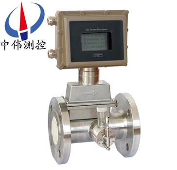
One-piece gas turbine flowmeter
ZW - LWQ seriesThe integration of gas turbine flowmeterAdvanced ultra low power single chip microcom…
Description:
ZW - LWQ seriesThe integration of gas turbine flowmeterAdvanced ultra low power single chip microcomputer technology of turbine flow sensor and display the integration of integrating new intelligent instrument, through the micro processing unit consists of temperature and pressure testing of analog channel, the flow sensor channel acquisition signal is carried out in accordance with the gas equation of temperature and pressure compensation, automatic compression factor correction, on the LCD screen will all data (instantaneous flow and cumulative flow rate and the total cumulative flow, temperature, pressure, time, date and battery) intuitive display, and to output condition, standard of pulse signal, 4-20 ma, RS485 communication and so on the many kinds of communication signals.
Second, the working principle:
ZW - LWQ seriesThe integration of the working principle of gas turbine flowmeter is a fluid flowing through the sensor shell, as a result of the impeller blade and flow to a certain point of view, the impact of fluid blade with rotational torque, to overcome the friction torque and fluid resistance, blade rotation speed stability after the moment balance, under certain conditions, the speed is proportional to the velocity of flow, because there are magnetic conductivity blade, it is in the signal detector (composed of * magnetic steel and coil) magnetic field, rotating blade cutting lines, periodically changing coil magnetic flux, so that the coil ends induction electrical pulse signal, the signal after amplifier amplification plastic, form a certain amplitude of continuous rectangular pulse wave, can be spread far to display instrument, show the instantaneous flow and cumulative amount of fluid.Within the scope of a certain flow, pulse frequency f and flows through the sensor of fluid is proportional to the instantaneous flow rate Q, flow equation is: Q = 3600 x f/k;Type:
F - pulse frequency (Hz);
K - the instrument coefficient of sensor 1 / m3, given by the check list.If [1 / L] as the unit
Q - fluid transient flow (working conditions) (m3 / h),
3600 - conversion factor.
Coefficient of each sensor of the instrument in the calibration certificate will be completed by the manufacturer, set into the display instrument of form a complete set of k value, can show the instantaneous flow and cumulative total.
Applications:
ZW - LWQ seriesIntegration of gas turbine flowmeter is learned the flow meter at home and abroad advanced technology optimized design, integrated the theory of gas mechanics, fluid mechanics, electromagnetism and developed a new generation of high precision, high reliability of gas precision measuring instrument, has a good performance of low pressure and high pressure measurement, multiple way signal output and low sensitivity to the fluid disturbance, is widely used in natural gas, coal gas, liquefied gas and light hydrocarbon gas and gas metering.
Four, display function:
1, according to standard criteria for instantaneous flow and cumulative flow;
2, according to working condition of the working condition of the instantaneous flow and cumulative flow;
3, according to the current pressure, temperature, battery voltage;
4, shows the date and the clock.
Five, the classification:
1, LWQ ZW - - A remote display: output current (match display instrument);
2, ZW - LWQ - B scene shows: seven LCD display, cumulative flow unit (m3) seven instantaneous flow, LCD display unit (m3 / h) (with Chinese characters display operator);
3, ZW - LWQ - C scene shows: the scene shows with 4 ~ 20 ma or pulse output + 24 v power supply;
4, ZW - LWQ - D temperature and pressure compensation type.
Six, the main features:
1, wide measuring range, the lower velocity of less than 0.5 m/s, small pressure loss, the impeller impact resistant ability.
2, has the high resistance to electromagnetic interference and vibration resistance, self-lubricating bearing adopts full sealing isolation protection, performance reliable working life is long.
3, USES the advanced ultra low power single chip microcomputer technology, the whole machine function is strong, low power consumption, superior performance.With nonlinear compensation function of intelligent traffic monitor precision.Accuracy is better than that of plus or minus 0.02%.
4, meter coefficient can be set up by the key online and can be displayed on the LCD screen, LCD screen clear intuitive, high reliability.
5, block the EEPROM for cumulative flow, instrument coefficient of power-fail protection.To protect more than 10 years.
6, can be in the measured gas pressure compensation under stable state of stress.
Seven, the technical parameters:
1, the nominal diameter: pipeline: DN4 DN200 ~;Insert: DN100 ~ DN2000;
2, precision grade: pipeline: plus or minus 0.5, plus or minus 1.0 on the Richter scale;Plug-in: 1.5 mm, 2.5 mm;
3, environmental temperature: - 20 ℃ to 50 ℃;
4, medium temperature: liquid measurement: - 20 ℃ ~ 120 ℃;Measuring gas: - 20 ℃ ~ 80 ℃;
5, the atmospheric pressure: 86 kpa to 106 kpa.
6, nominal pressure: 1.6 Mpa, 2.5 Mpa, 6.4 Mpa, 25 Mpa;
7, explosion-proof level: ExdIIBT4;
8, connection mode: threaded connection, flange clamp outfit, flange connection, plug, etc;
9, straight pipe requirements: gas: a straight pipe upstream should be 10 or more dn, downstream straight pipe should be 5 or more dn.
Liquid: straight pipe upstream should be 20 or more dn, downstream straight pipe should be 5 or more dn.
Plug-in: straight pipe upstream should be 20 or more DS, downstream straight pipe should be 7 or higher DS (DS for pipeline measured diameter);
10, the display mode:
(1) far eastone show: pulse output, the output current (match display instrument);
(2) the scene showed that eight LCD display cumulative flow, unit (m3);
Four transient flow, LCD display unit (m3 / h), battery, frequency, flow velocity;
(3) the temperature and pressure compensation type:
A, according to standard criteria for instantaneous flow and cumulative flow;
B, show the current pressure, temperature, battery voltage;
11, output functions:
(1) pulse output, p - p values determined by power supply;
Two wire (2) 4 ~ 20 ma current output;
(3) pulse output per unit volume and the original pulse sensor output;
(4) with RS485 communication interface;
12, power supply:
(1)DC5~24V;
(2) the standard 3 v lithium battery installed on the instrument internal can use eight consecutive years;
(3) temperature pressure compensation type 3 v lithium battery installed within the instrument can be continuous use of more than 4 years;
13, transmission distance, to display, sensors can reach 500 m;
Eight, instrument type:
A, the scene display type:
The intelligent flowmeter is the use of advanced single chip microcomputer technology design of the new display instrument of the flow meter, and the flow sensor of pulse signal output form a complete set.It can display instantaneous flow and cumulative amount.Cumulative flow: eight digit, decimal point three significant figures.Instantaneous flow: six figures, but showed a litre.Display precision: plus or minus a display unit.Signal output: pulse output: 1 ~ 3000 hz for + 12 ~ + 24 VDC power supply output current: 4 ~ 20 ma away for + 24 VDC power supply (two wire system) built-in 2 section 3 v lithium battery power supply in parallel.When the voltage is lower than 2.7 V, the under-voltage directives flameproof.Small signal removal function.
B, pulse output type:
Working voltage: + + 12 VDC or 24 VDC two (customer order must be selected before a power supply).Signal transmission distance: less than 250 meters.Output signal, square wave signal amplitude: + 12 VDC power supply amplitude is about 10 v + 24 VDC power supply amplitude of about 20 v: amplifier and turbine flow sensor connection for the M16 x 1.5 thread, after the turbine flow sensor installation, twist to the turbine flow sensor, the amplifier with the hand twist to sense amplifier and then take the lock nut.Connection: type pulse output amplifier foreign lead with three root, red, white line and shielding.Is the power supply line, white line for pulse output and display, or other equipment connection, shielding grounding
C, 4 ~ 20 ma output type:
Outside the working voltage: 24 VDC power supply + (two wire system) output signal: 4 ~ 20 ma, or 1, 4-5 v ma corresponding to zero flow turbine flow sensor, 20 ma for turbine flow sensor zui large flow, flow range turbine flow sensor nameplate.Signal transmission distance: less than 250 meters.After the installation of turbine flow sensor installation, twist the amplifier to the turbine flow sensor (m16 x 1.5 thread), joint hands after twist to the sense amplifier has exactly bring tight lock nut.Connection: 4 ~ 20 ma output type amplifier foreign fuses with the red and white line.The red line for the power cord, white line for line.
D, fission remote display type:
Outside power supply working voltage: 220 vac signal transmission distance: less than 250 meters display instantaneous four: accumulative total nine display display size: horizontal type: 160 mm x 80 mm upright: 80 mm x 160 mm display with 4 ~ 20 ma output and can be connected to the computer.
Nine, structure and installation method:
1, instrument installation using thread connection and clamp type;
2, liquid flow direction when installation should be direction of arrow and indicating flow sensor shell, and a straight pipe upstream should be 6 D, or downstream straight pipe should be 5 D or higher measured pipeline measured diameter (D).
3, sensors should be far away from the external magnetic field, such as can't be avoided, necessary measures should be taken;
4, in order to not affect the normal delivery of the liquid, maintenance should be straight section on opposite sides of the sensor installation outside the by-pass pipe;
5, sensors, outdoor installation time, please prepare amplifier plug waterproof processing;
6, sensor and display instrument connection, should according to the power of the amplifier to choose connection mode, as shown in the relevant specification.
Ten, wiring and grounding considerations:
Wiring matters needing attention
1, using a full cable as soon as possible.
2, should as far as possible away from electrical noise (such as power transformer, electric motor and the power cord), avoid parallel to the power the power cord wiring.
3, Suggestions in the end of the thick wire adopts the tin welding clamping lugs.
4, for the waterproof and mechanical damage, the cable into the metal tube inside, but may not have high power transmission cables, within the same catheter (a transmission cable transmission of zui power is greater than the flowmeter signal transmission cables zui small power 10 times, both cannot be installed on the same catheter).
5, the existing strong magnetic field outside the area, should make the axis of the detection device with the outside world vertical or the direction of the magnetic flux of the magnetic field with high permeability material for shielding flow sensor or external magnetic source.
6, explosion-proof type turbine flow sensor cable connection, must strictly abide by the relevant standards of explosion-proof amplifier.
Eleven, installation location:
1, the installation site should comply with the environmental temperature at 25 ~ 55 ℃ scope, humidity < 80% RH;
2, well ventilated, avoid sun and rain;
3, avoid in piping vibration or the place of stress;
4, avoid easily affected by the strong thermal radiation and radioactive places;
5, must avoid the outside strong electromagnetic field disturbance to the detection signal.If unavoidable, should be set on the amplifier of the flowmeter (sensor) shield and other measures to eliminate interference;
6, in the places where requires explosion-proof, and isolation amplifier should be adopted;
7, the installation position should consider ease of installation, operation, maintenance.
Twelve, installation reasons may lead to the problem:
1, the length of straight pipe upstream or downstream is insufficient;
2, instrument measuring pipe diameter and pipe diameter deviation;
3, install different heart, gasket convex tube;
4, instrument going backward;
5, detecting element is covered by impurities;
6, reduce the detection sensitivity, small leakage flow meter;
7, pipeline leak (installed in underground pipeline, for example, small leakage was found), valve leakage, by-pass valve leakage cause cumulative flow smaller (total);
8, there are two phase flow, pulsating flow influence the accurate measurement.
thirteen, storage precautions:
Gas turbine arrival should be installed in a timely manner.For a battery-powered LRT -i header, not when using the power pin should be placed in the "OFF" (OFF) position, in order to avoid battery depletion affect the service life of the battery.If you want to deposit, please pay attention to the following items:
A, the possible conditions, do not open the packing cases.
B, if already opened the package, or have used the instrument, please put the LRT -i header power jumper wire inserted in the "OFF" position, and use the original packaging.
Location should meet the following conditions:
A, rain moistureproof.
B, small mechanical vibration, avoid collision impact.
C, temperature in - 30 ~ + 60 ℃.The ideal temperature at 25 ℃ or so.
D, such as stored in outdoor, instrument performance will be affected.So if the instrument to the installation location, will install as soon as possible.
14, notable matters of installation:
1, before setting, pipeline purging cleaning, in case the residual iron affect the deformation of flowmeter operation.Before the installation, use and easy flow blowing turbine, the turbine can turn the motor, and no random noise, filling ink revealed performance is normal, the meter can be installed applications.Grace flow meter installed at the flange pipe flange two head to also add sealing washer.Meter shall be equipped with filters, temperament is dirty places should be equipped with oil filter, before you place an order, can order to my company at the same time, it is strictly prohibited to filter attached directly to the flowmeter.
2, successively when installation should be added by the valve.Flange coherent pipe diameter in adjacent shall not have arisen.To install flowmeter, it is strictly prohibited in its development into the inlet flange place directly welding, province burn Clinton meter outside the machine.Meter should be installed in easy to repair, no strong electromagnetic dry heat invasion, the places where machine vibration and thermal radiation effects.Frequent flowmeter was used in the traffic and the end of the places where violent pulsating flow or pressure pulsation.Meter outdoor installation, should be the upper cover, to prevent rain in the scorching sun exposure, affect the service life of the meter.Flow meter can be installed in vertical or horizontal, fluid motion should be partial to be partial to different with logo on the shell, the flow meter of crude should can have not less than 10 dn straight pipe, after the table is not less than 5 dn straight pipe.
3, walked in order not to affect the normal fluid, pioneered by figure 2 install bypass pipe, the misshapen make diachronic must close the by-pass pipe valves.In pipeline construction, should try to install about telescopic pipe or bellows, in order to avoid the flow meter of serious tension or fracture;Should indeed life entrance and flowmeter and import of adjacent coaxial, and avoid washer and weld, into the pipe or disturbs the flow profile.Adopt external power, the flow meter must be reliable grounding, but shall not be Shared with heavy current futile ground, when pipeline installation or maintenance, can't leave the ground and flowmeter lap welding futile.Pipeline sealing test set to complete development, should hope that flowmeter pressure sensor can suffer zui high pressure (i.e., zui appraisal certificate on medium pressure), in order to avoid damage of Clinton pressure sensor.
15, parameter table:
Instrument model | ZW-LWQ-N | ZW-LWQ-A | ZW-LWQ-B | ZW-LWQ-C | ZW-LWQ-D |
Signal output | pulse | 4-20mA | There is no | 4-20mA | Optional 4-20 ma/pulse |
Power supply | +24VDC±15% | +24VDC±15% | The lithium battery | 24VDC±15% | 24 VDC plus or minus 15% + lithium battery |
Precision grade | 2.5 ~ 1.5 on the Richter scale are unlikely | 1.5 ~ 1.0 on the Richter scale are unlikely | 1.5 ~ 1.0 on the Richter scale are unlikely | ||
Measuring range | The standard range | Standard range or extension | Standard range or extension | ||
display | There is no | There are | There are | ||
Temperature, pressure compensation | There is no | There is no | There are | ||
Communication interface | There is no | There is no | RS485 | ||
Real time record | There is no | There is no | There are | ||
Instrument material | Aluminum alloy or stainless steel | Aluminum alloy or stainless steel | Aluminum alloy or stainless steel | ||
Explosion-proof grade | ExdIIBT6 or ExiaIICT4 | ExdIIBT6 or ExiaIICT4 | ExdIIBT6 or ExiaIICT4 | ||
Protection grade | IP65 | IP65 | IP65 | ||
The machine power consumption | < 1W | < 1W | < 1W | ||
Instrument drift diameter | DN25~DN300 | DN25~DN300 | DN25~DN300 | ||
installation | Flange installation | Flange installation | Flange installation | ||
Medium temperature | - 20 ℃ ~ 80 ℃ | - 20 ℃ ~ 80 ℃ | - 20 ℃ ~ 80 ℃ | ||
The environment temperature | - 30 ℃ ~ 60 ℃ | - 30 ℃ ~ 60 ℃ | - 30 ℃ ~ 60 ℃ | ||
16, measurement range and pressure rating:
Nominal diameter | model | The standard range | Extended range | Stress levels | High pressure rating | installation |
DN20 | ZW-LWQ-20 | 2.2-25 | 4-40 | 1.6 | 2.5, 4.0 | The flange |
DN25 | ZW-LWQ-25 | 2.2-25 | 4-40 | 1.6 | 2.5, 4.0 | Flange (thread) |
DN32 | ZW-LWQ-32 | 5-50 | 6-60 | 1.6 | 2.5, 4.0 | The flange |
DN40 | ZW-LWQ-40 | 5-50 | 6-60 | 1.6 | 2.5, 4.0 | Flange (thread) |
DN50 | ZW-LWQ-50 | 6-65 | 5-70. | 1.6 | 2.5, 4.0 | The flange |
ZW-LWQ-50 | 10-100. | 8-100. | ||||
DN65 | ZW-LWQ-65 | 15-200. | 10-200. | 1.6 | 2.5, 4.0 | The flange |
DN80 | ZW-LWQ-80 | 13-250. | 10-160. | 1.6 | 2.5, 4.0 | The flange |
ZW-LWQ-80 | 20-400. | The flange | ||||
DN100 | ZW-LWQ-100 | 20-400. | 13-250. | 1.6 | 2.5 | The flange |
ZW-LWQ-100 | 32-650. | The flange | ||||
DN125 | ZW-LWQ-125 | 25-700. | 20-800. | 1.6 | 2.5 | The flange |
DN150 | ZW-LWQ-150 | 32-650. | 80-1600. | 1.6 | 2.5 | The flange |
ZW-LWQ-150 | 50-1000. | The flange | ||||
DN200 | ZW-LWQ-200 | 80-1600. | 50-1000. | 1.6 | ... | The flange |
ZW-LWQ-200 | 130-2500. | The flange | ||||
DN250 | ZW-LWQ-250 | 130-2500. | 80-1600. | 1.6 | ... | The flange |
ZW-LWQ-250 | 200-4000. | The flange | ||||
DN300 | ZW-LWQ-300 | 200-4000. | 130-2500. | 1.6 | ... | The flange |
320-6500. | 1.6 |
The 17th and selection code:
type | ZW□□□ | - | - | - | - | Instructions (in the wei and control) | |||
LWQ-N | Basic three-wire system output pulse signal,+24VThe power supply | ||||||||
LWQ-A | Current output type4~20mAThe output,+24VThe power supply | ||||||||
LWQ-B | The display type3.6VBattery power | ||||||||
LWQ-C | The scene shows with4~20mAOr pulse output;+24VThe power supply | ||||||||
LWQ-D | Flow transmitter4~20mAThe output,+24VThe power supply.Temperature pressure compensation type | ||||||||
Nominal diameter | 20 | The normal flow The scope ofm3/h | 2.5-25 m3/h | Expand the flow The scope ofm3/h | 4-40 m3/h | ||||
25 | 2.5-25 m3/h | 4-40 m3/h | |||||||
32 | 5-50 m3/h | 6-60 m3/h | |||||||
40 | 5-50 m3/h | 6-60 m3/h | |||||||
50 | 6-65 m3/h | 5-70 m3/h | |||||||
65 | 15-200m3/h | 10-200m3/h | |||||||
80 | 13-250 m3/h | 10-160 m3/h | |||||||
100 | 20-400 m3/h | 13-250 m3/h | |||||||
125 | 25-700m3/h | 20-800 m3/h | |||||||
150 | 32-650 m3/h | 50-1000 m3/h | |||||||
200 | 80-1600 m3/h | 800-1600 m3/h | |||||||
250 | 130-2500 m3/h | 80-1600 m3/h | |||||||
300 | 200-4000 m3/h | 320-6500 m3/h | |||||||
explosion-proof | No mark for the explosion proof type | ||||||||
B | Explosion-proof type | ||||||||
Precision grade | A | precision1.0level | |||||||
B | precision1.5level | ||||||||
C | precision2.5level | ||||||||
The turbine type | A | Normal flow range | |||||||
B | Expand the flow range | ||||||||
For example, the model is:ZW-LWQ-C-50-B-A-AThe gas turbine flowmeter, said:
Meter diameter for50mm, display and output way of live shows, the output current for measuring precision1.0%;Turbine types are measured normal flow range of one-piece type gas turbine flowmeter.
Eighteen, designing order selection guidelines:
1, instrument selection, as far as possible not to use the work flow in the lower limit value, so the meter diameter should be as small as possible, in order to obtain a larger flow rate and flow range.
2, the flowmeter should be used in the technical parameters of medium pressure and temperature range.Don't deliberately choose the high pressure level and ultra-high temperature instrument, should be selected according to the actual work pressure and temperature instruments, which had higher prices.
3, in the explosive dangerous location, should choose explosion-proof type flowmeter.
4, the lower limit of flowmeter flow depends on the operation condition of the medium density and kinematic viscosity, the maximum flow is generally not affected by medium pressure and temperature, so to determine the flow range as long as you determine the actual minimum flow can be available.Calculate the minimum flow rate, flow range check table to determine the appropriate diameter.
After-sales service commitment:
1, from the date of signing of the contract, I in the way provided for products of the company offers free maintenance and maintenance service, commitment to lifelong maintenance service;
2, jiangsu wei measurement and control instrument co., LTD. Sales manager will be in regular contact with customers, understand the usage of products, and solve the problems of the customers to use in the process of produce, free of charge to provide technical support;
3 the man-made damage is found, the warranty period, our company is responsible for the maintenance, and the resulting maintenance fee;
4, product quality problems or are not satisfied with product, the user can choose unconditional return, wei tt&c don't charge any fees, appear quality problem, bear the freight back and forth.
Browse:
