
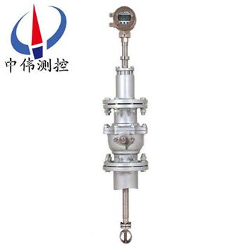
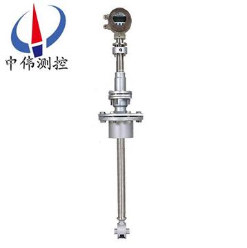
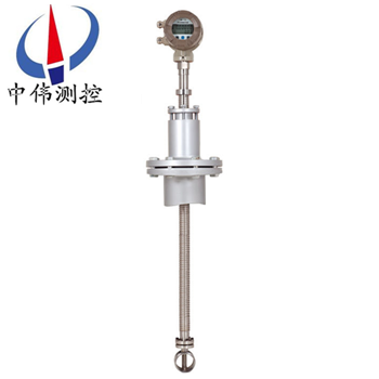

Products overview:
ZW series of LWCInsert the turbine flow meterIs a kind of precise flow measuring instrument, ZW - LWCQ (tangent) and ZW - LWCB (axial) insert type turbine flow sensor (sensor) and display instrument accessories, componentsTurbine flowmeter, can be widely used in petroleum, chemical industry, metallurgy, paper making industries such as measuring the volume of fluid transient flow and the total volume.
The turbine flowmeter for explosion-proof structure design, can display the total flow, instantaneous flow and flow full percentage.Battery USES the long-lasting lithium-ion batteries, single-function integrating table battery service life can reach more than 5 years, multi-function display table battery service life also can achieve more than 12 months.
ZW series of LWC plug-in turbine meter can display the flow unit is numerous, cubic meters, gallons, liters, standard cubic meters, the standard and can be set fixed parameters of gas pressure and temperature compensation, little change in the situation of pressure and temperature parameters, the instrument can be used for integrating fixed compensation.
Second, the working principle:
ZW series of LWC plug-in working principle of turbine flowmeter is a fluid flowing through the sensor shell, as a result of the impeller blade and flow to a certain point of view, the impact of fluid blade with rotational torque, to overcome the friction torque and fluid resistance, blade rotation speed stability after the moment balance, under certain conditions, the speed is proportional to the velocity of flow, because there are magnetic conductivity blade, it is in the signal detector (composed of * magnetic steel and coil) magnetic field, rotating blade cutting lines, periodically changing coil magnetic flux, so that the coil ends induction electrical pulse signal, the signal after amplifier amplification plastic, form a certain amplitude of continuous rectangular pulse wave, can be spread far to display instrument, show the instantaneous flow and cumulative amount of fluid.Within the scope of a certain flow, pulse frequency f and flows through the sensor of fluid is proportional to the instantaneous flow rate Q, flow equation is: Q = 3600 x f/k;Type:
F - pulse frequency (Hz);
K - the instrument coefficient of sensor 1 / m3, given by the check list.If [1 / L] as the unit
Q - fluid transient flow (working conditions) (m3 / h),
3600 - conversion factor.
Coefficient of each sensor of the instrument in the calibration certificate will be completed by the manufacturer, set into the display instrument of form a complete set of k value, can show the instantaneous flow and cumulative total.
Three, the main features:
The characteristics of ZW - LWCQ:
1, strong ability to resist the impurities, tangential impeller rotating at can release floating debris in the fluid at any time, when the winding on tangential impeller blades
Resistance to electromagnetic interference and strong ability of anti vibration;
2, the structure and principle of the sensor and display instrument are very simple and intuitive, and users especially easy to master its use and maintenance technology;
After 3, replacing the impeller and bearing, instrument coefficient;
4, wide flow range, minimum flow rate is low;
5, complete sets of flow meter for the measurement of the fluid volume error is small;
6, almost no pressure loss, saving power consumption;
7, the sensor can be installed in open air, the sensor can be submerged in water for a long time to use;
8, a cut-off valve sensor, the installation and disassembly are not stop;
Nine, horizontal, vertical and inclined pipe are used;
10, the purchase of complete sets of flowmeter, installation and maintenance cost is low.
The characteristics of ZW - LWCB:
1, the structure and principle of the sensor and display instrument are very simple and intuitive, and users especially easy to master its use and maintenance technology;
2, resistance to electromagnetic interference and vibration-proof ability;
After 3, replacing the impeller and bearing, instrument coefficient;
4, wide flow range, minimum flow rate is low;
5, complete sets of flow meter for the measurement of the fluid volume error is small;
6, almost no pressure loss, saving power consumption;
7, the sensor can be installed in open air, the sensor can be submerged in water for a long time to use;
8, a cut-off valve sensor, the installation and disassembly are not stop;
Nine, horizontal, vertical and inclined pipe are used;
10, the purchase of complete sets of flowmeter, installation and maintenance cost is low.
Four, the technical parameters:
1, meter diameter: threaded connections: 4, 6, 10, 15, 20, 25, 32, 40;
Flange connection: (15, 20, 25, 32, 40, 50, 65, 80, 100, 125, 150, 200;
Insert: more than 200;
2, range scale: 1:10;1:15.1;
3, instrument material: stainless steel 304, 316 (L) stainless steel, etc;
4, medium temperature: - 20 ℃ ~ + 120 ℃;
5, environmental temperature: - 10 ℃ ~ + 55 ℃;
6, relative humidity: 5% ~ 9%;
7, the atmospheric pressure: 86 ~ 106 kpa;
8, power supply: the scene display type: instrument with lithium batteries;
9, explosion-proof forms: basic not explosion-proof, explosion-proof type;
10, protection grade: IP65, IP67.
Five, the structure and installation method:
1, instrument installation using thread connection and clamp type;
2, liquid flow direction when installation should be direction of arrow and indicating flow sensor shell, and a straight pipe upstream should be 6 D, or downstream straight pipe should be 5 D or higher measured pipeline measured diameter (D).
3, sensors should be far away from the external magnetic field, such as can't be avoided, necessary measures should be taken;
4, in order to not affect the normal delivery of the liquid, maintenance should be straight section on opposite sides of the sensor installation outside the by-pass pipe;
5, sensors, outdoor installation time, please prepare amplifier plug waterproof processing;
6, sensor and display instrument connection, should according to the power of the amplifier to choose connection mode, as shown in the relevant specification.
Six, wiring and grounding considerations:
Wiring matters needing attention
1, using a full cable as soon as possible.
2, should as far as possible away from electrical noise (such as power transformer, electric motor and the power cord), avoid parallel to the power the power cord wiring.
3, Suggestions in the end of the thick wire adopts the tin welding clamping lugs.
4, for the waterproof and mechanical damage, the cable into the metal tube inside, but may not have high power transmission cables, within the same catheter (a transmission cable transmission of zui power is greater than the flowmeter signal transmission cables z small power of 10 times, both cannot be installed on the same catheter).
5, the existing strong magnetic field outside the area, should make the axis of the detection device with the outside world vertical or the direction of the magnetic flux of the magnetic field with high permeability material for shielding flow sensor or external magnetic source.
6, explosion-proof type turbine flow sensor cable connection, must strictly abide by the relevant standards of explosion-proof amplifier.
Grounding problem
1, the shielding wire can only be grounded at one end, on display instrument grounding.
2, reliable grounding should be good, explosion-proof type grounding resistance should be less than 10 Ω.
The use of turbine flow time must pay attention to the points:
1, requires clean measured medium, low viscosity, corrosion resistance is small, do not contain impurities, in order to reduce the wear of bearing.If the liquid to be measured a grudge or containing gas, the flowmeter before venting device.In order to avoid damage of impurity in the fluid into the transmitter devious, and in order to prevent turbine stuck, add filters when necessary.
2, the installation of the flowmeter should avoid vibration, avoid magnetic field and thermal radiation.
3, medium density and viscosity changes have an impact on flow value, should be revised if necessary.
Seven, the installation place:
1, the installation site should comply with the environmental temperature at 25 ~ 55 ℃ scope, humidity < 80% RH;
2, well ventilated, avoid sun and rain;
3, avoid in piping vibration or the place of stress;
4, avoid easily affected by the strong thermal radiation and radioactive places;
5, must avoid the outside strong electromagnetic field disturbance to the detection signal.If unavoidable, should be set on the amplifier of the flowmeter (sensor) shield and other measures to eliminate interference;
6, in the places where requires explosion-proof, and isolation amplifier should be adopted;
7, the installation position should consider ease of installation, operation, maintenance.
Eight, matters needing attention in use:
(1) performing instrument coefficient of the turbine flowmeter was put before you set, carefully check, determine the flow meter wiring and correct, grounding good rear can send;
(2) regular flowmeter for cleaning, inspection and after school, lubricating oil or cleaning fluid into the mouth of the flowmeter, should be regularly according to the requirement of the specifications into lubricating oil or cleaning fluid, to maintain good impeller;
(3) monitoring display instrument, estimates the meter reading, with exception to check in time;
(4) keep clear of the filter, filter clogging situation from the entrance and exit the increase of the differential pressure gauge readings to determine, a blockage in a timely manner to eliminate;
(5) with turbine flowmeter for trade settlement, in order to ensure accurate and reliable measurement, must test on a regular basis.
Nine, parameter table:
Instrument specifications | Cut to the plug-inZW-LWCQ | The axial plug-inZW-LWCB |
The mounting way | Cut-out after disassembling | Do not need to stop, then closed ball valve and dismantling |
Instrument model | Atype | Btype |
precision | Plus or minus 2.5% | Plus or minus 2.5% |
display | optional | optional |
The output signal | Optional: pulse or4-20mA | Optional: pulse or4-20mA |
Communication interface | optionalRS485 | optionalRS485 |
Power supply | +24VDC±15% | +24VDC±15% |
Explosion-proof grade | optionalExdIIBT6orExiaIICT4 | optionalExdIIBT6orExiaIICT4 |
Protection grade | IP65 | IP65 |
The machine power consumption | <1W | <1W |
Instrument material | 304SS | 304SS |
Nominal pressure | 1.0MPa | 1.0MPa |
Temperature range | - 20℃ ~120℃ | - 20℃ ~120℃ |
The environment temperature | - 20℃ ~70℃ | - 20℃ ~70℃ |
Requirement for straight pipe length: sensors upstream straight pipe length should not be less than20DN, downstream straight pipe length should not be less than7DNTo ensure measurement accuracy.If straight pipe length can't meet this requirement, can have the calibration with conditions of site after calibration, the in-situ calibration of the meter coefficientK。
Ten, measuring range:
1、LWCQNominal diameterandFlow range:
model | Pipeline measured diametermm | Insert stem lengthmm | Corresponding to the nominal diameterDNThe flow rangem3/h | ||
The whole flow range | |||||
LWCQ-100 | 100 | 6-150 | LWCQ-100 | 100 | |
LWCQ-150 | 150 | 13-200. | LWCQ-150 | 150 | |
LWCQ-200 | 200 | 23-300. | LWCQ-200 | 200 | |
LWCQ≤400 | 100 | 906 | 6-150 | LWCQ≤400 | 100 |
150 | 13-200. | 150 | |||
200 | 23-300. | 200 | |||
250 | 36-450. | 250 | |||
300 | 52-650. | 300 | |||
350 | 70-900. | 350 | |||
400 | 92-1100. | 400 | |||
LWCQ≤800 | 500 | 1106 | 150-1800. | LWCQ≤800 | 500 |
600 | 220-2500. | 600 | |||
700 | 280-3500. | 700 | |||
800 | 380-4500. | 800 | |||
LWCQ>800 | 900 | 1306 | 460-5800. | LWCQ>800 | 900 |
1000 | 600-7000. | 1000 | |||
1100 | 700-8500. | 1100 | |||
2、LWCBNominal diameterandFlow range:
model | Pipeline measured diametermm | Insert stem lengthmm | Corresponding to the nominal diameterDNThe flow rangem3/h | ||
The whole flow range | Accurate forPlus or minus 2.5%the | The accuracy ofPlus or minus 5% | |||
LWCB-100 | 100 | 3-150. | 5-150. | < 5 to 3 | |
LWCB-150 | 150 | 7-200. | 10-200. | The < 10-7 | |
LWCB-200 | 200 | 12-300. | 20-300. | < 20-12 | |
LWCB≤400 | 100 | 900 | 3-150. | 5-150. | < 5 to 3 |
150 | 7-200. | 10-200. | The < 10-7 | ||
200 | 12-300. | 20-300. | < 20-12 | ||
250 | 18-450. | 31-450. | < 31-18 | ||
300 | 26-650. | 45-650. | < 45-26 | ||
350 | 35-900. | 60-900. | < 60-35 | ||
400 | 46-1100. | 80-1100. | < 80-46 | ||
LWCB≤800 | 500 | 1100 | 75-1800. | 125-1800. | < 125-75 |
600 | 110-2500. | 180-2500. | < 180-110 | ||
700 | 140-3500. | 225-3500. | < 225-140 | ||
800 | 190-4500. | 320-4500. | < 320-190 | ||
LWCB>800 | 900 | 1300 | 230-5800. | 400-5800. | < 400-230 |
1000 | 300-7000. | 495-7000. | < 495-300 | ||
1100 | 350-8500. | 600-8500. | < 600-350 | ||
Eleven, selection of coding:
model | Specifications and codes | instructions |
ZW-LWC | Insert the turbine flow sensor (wei measurement and control) | |
B | Ball valve plug (axial) | |
Q | Simple plug-in (tangent) | |
Y | Liquid pipeline | |
Nominal diameter | 2 - | 2mm(pipe threadG3/8″) |
4 - | 4mm(pipe threadG1/2″) | |
- 6 | 6mm(pipe threadG1/2″) | |
- 10 | 10mm(pipe threadG1/2″) | |
- 15 | 15mm(pipe threadG1″) | |
- 25 | 25mm(pipe threadG11/4″) | |
- 40 | 40mm(The flange type) | |
- 50 | 50mm(The flange type) | |
- 80. | 80mm(The flange type) | |
- 100. | 100mm(The flange type) | |
- 150. | 150mm(The flange type) | |
- 200. | 200mm(The flange type or plug-in) | |
- 250. | 250mm(The flange type or plug-in) | |
- 300. | 300mm(The flange type or plug-in) | |
Precision grade | A | precision2.5% |
B | precision1.0% | |
C | precision0.5% | |
Signal output | M | Integration of liquid crystal display and belt4~20mAOutput current |
J | Supporting for separated flow totalizer.especially display | |
S | Form a complete set of fission flow totalizer.especially display and output4~20mA | |
I | 4~20mAOutput current | |
T | The integration of liquid crystal display (LCD) | |
P | Pulse output | |
Nominal pressure | C1 | PN1.61111MPa |
C2 | PN2.5111MPa | |
C3 | PN4.0111MPa | |
C4 | PN6.3111MPa | |
C5 | PN16MPa | |
C6 | PN25MPa | |
C7 | PN40MPa | |
Explosion-proof requirements | / NE | Don't riot |
/EX | Explosion-proof gradedⅡBT4 | |
Temperature requirements | / NE | The normal temperature |
/HE | 120℃pThe high temperatureP 150℃ | |
Other requirements | /□ | Noted when ordering |
Twelve, designing order selection guidelines:
1, instrument selection, as far as possible not to use the work flow in the lower limit value, so the meter diameter should be as small as possible, in order to obtain a larger flow rate and flow range.
2, the flowmeter should be used in the technical parameters of medium pressure and temperature range.Don't deliberately choose the high pressure level and ultra-high temperature instrument, should be selected according to the actual work pressure and temperature instruments, which had higher prices.
3, in the explosive dangerous location, should choose explosion-proof type flowmeter.
4, the lower limit of flowmeter flow depends on the operation condition of the medium density and kinematic viscosity, the maximum flow is generally not affected by medium pressure and temperature, so to determine the flow range as long as you determine the actual minimum flow can be available.Calculate the minimum flow rate, flow range check table to determine the appropriate diameter.
After-sales service commitment:
1, from the date of signing of the contract, I in the way provided for products of the company offers free maintenance and maintenance service, commitment to lifelong maintenance service;
2, jiangsu wei measurement and control instrument co., LTD. Sales manager will be in regular contact with customers, understand the usage of products, and solve the problems of the customers to use in the process of produce, free of charge to provide technical support;
3 the man-made damage is found, the warranty period, our company is responsible for the maintenance, and the resulting maintenance fee;
4, product quality problems or are not satisfied with product, the user can choose unconditional return, wei tt&c don't charge any fees, appear quality problem, bear the freight back and forth.
