
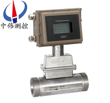
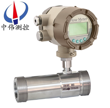

Products overview:
ZW - LW seriesThread linking turbine flowmeterIs composed of turbine flow sensor and display instrument, is our factory adopts the advanced foreign technology manufacturing is one of liquid measurement zui ideal flowmeter.Flow meter has simple structure, high precision, convenient in installation and maintenance, etc.The products are widely used in petroleum, chemical industry, metallurgy, water supply, paper making, environmental protection, food and other fields, and is suitable for the measurement in a closed pipe with 1 cr18ni9ti stainless steel, 2 cr13 and corrode corundum Al2O3, cemented carbide, and no fiber, particle impurities such as liquid.If with display instrument with special functions, can automatically quantitative control, such as excessive alarm purposes.
Second, the working principle:
ZW - LW seriesThread link turbine flowmeter is when the fluid flows through the sensor shell, as a result of the impeller blade and flow to a certain point of view, the fluid force makes the blade with rotational torque, to overcome the friction torque and fluid resistance, blade rotation speed stability after the moment balance, under certain conditions, the speed is proportional to the velocity of flow, because the blade has a magnetic conductivity, it is in the signal detector (composed of * magnetic steel and coil) magnetic field, rotating blade cutting lines, periodically changing coil magnetic flux, so that the coil ends induction electrical pulse signal, the signal after amplifier amplification plastic, form a certain amplitude of continuous rectangular pulse wave, can be spread far to display instrument, show the instantaneous flow and cumulative amount of fluid.Within the scope of a certain flow, pulse frequency f and flows through the sensor of fluid is proportional to the instantaneous flow rate Q, flow equation is: Q = 3600 x f/k;Type:
F - pulse frequency (Hz);
K - the instrument coefficient of sensor 1 / m3, given by the check list.If [1 / L] as the unit
Q - fluid transient flow (working conditions) (m3 / h),
3600 - conversion factor.
Coefficient of each sensor of the instrument in the calibration certificate will be completed by the manufacturer, set into the display instrument of form a complete set of k value, can show the instantaneous flow and cumulative total.
Applications:
ZW - LW seriesThread linking turbine flowmeter is a kind of precise flow measuring instrument, and the corresponding supporting flow integrating instrument can be used to measure the rate of flow of liquid and the total amount.Widely used in petroleum, chemical industry, metallurgy, scientific research in the areas of measurement and control system.Equipped with health joints threaded connection type liquid turbine flowmeter sensor can be used in the pharmaceutical industry.
Four, the main features:
1, small pressure loss, impeller has antiseptic function.
2, has the high resistance to electromagnetic interference and shock resistant capacity, performance reliable working life is long.
3, USES the advanced ultra low power single chip microcomputer technology, the whole machine function is strong, low power consumption, superior performance.With nonlinear compensation function of intelligent flow display precision.
Device.The accuracy of correction formula is better than that of plus or minus 0.02%.
4, meter coefficient can be set up by the key online and can be displayed on the LCD screen, LCD screen clear intuitive, high reliability.
5, block the eeprom for cumulative flow, instrument coefficient of power-fail protection.To protect more than 10 years.
Five, the technical parameters:
1, the nominal diameter: pipeline: DN4 DN200 ~;Insert: DN100 ~ DN2000;
2, precision grade: pipeline: plus or minus 0.5, plus or minus 1.0 on the Richter scale;Plug-in: 1.5 mm, 2.5 mm;
3, environmental temperature: - 20 ℃ to 50 ℃;
4, medium temperature: liquid measurement: - 20 ℃ ~ 120 ℃;Measuring gas: - 20 ℃ ~ 80 ℃;
5, the atmospheric pressure: 86 kpa to 106 kpa.
6, nominal pressure: 1.6 Mpa, 2.5 Mpa, 6.4 Mpa, 25 Mpa;
7, explosion-proof level: ExdIIBT4;
8, connection mode: threaded connection, flange clamp outfit, flange connection, plug, etc;
9, straight pipe requirements: gas: a straight pipe upstream should be 10 or more dn, downstream straight pipe should be 5 or more dn.
Liquid: straight pipe upstream should be 20 or more dn, downstream straight pipe should be 5 or more dn.
Plug-in: straight pipe upstream should be 20 or more DS, downstream straight pipe should be 7 or higher DS (DS for pipeline measured diameter);
10, display mode: (1) far eastone show: pulse output, the output current (match display instrument);
(2) the scene showed that eight LCD display cumulative flow, unit (m3);
Four transient flow, LCD display unit (m3 / h), battery, frequency, flow velocity;
(3) the temperature and pressure compensation type:
A, according to standard criteria for instantaneous flow and cumulative flow;
B, show the current pressure, temperature, battery voltage;
11, output functions:
(1) pulse output, p - p values determined by power supply;
Two wire (2) 4 ~ 20 ma current output;
(3) pulse output per unit volume and the original pulse sensor output;
(4) with RS485 communication interface;
12, power supply:
(1)DC5~24V;
(2) the standard 3 v lithium battery installed on the instrument internal can use eight consecutive years;
(3) temperature pressure compensation type 3 v lithium battery installed within the instrument can be continuous use of more than 4 years;
13, transmission distance, sensors to display the distance up to 500 m.
Seven, the installation place:
1, the installation site should comply with the environmental temperature at 25 ~ 55 ℃ scope, humidity (80% RH
2, well ventilated, avoid insolation, drench
3, avoid in piping vibration or stress
4, avoid easily affected by the strong thermal radiation and radioactive
5, must avoid the outside strong electromagnetic field disturbance to the detection signal.If unavoidable, should be set on the amplifier of the flowmeter (sensor) shield and other measures to eliminate the interference.
6, in the places where requires explosion-proof, and isolation amplifier should be adopted
7, the installation position should consider ease of installation, operation, maintenance
Eight, directions for use:
Measured liquid 1, when using, should maintain clean, do not contain impurities such as fiber and particles.
2, sensors, at the beginning of the use should be to slowly filled with liquid sensor, and then open the outlet valve (the valve should be installed in the back-end flow meters), it is strictly prohibited to sensors in liquid state under high velocity impact.
The maintenance period of 3, sensors, generally for half a year.Maintenance when cleaning, please note that you are the measuring chamber of damaged parts, especially in the impeller.Please watch the orientation and the position of the impeller when assembling.
4, sensors, need not when, should be clean inside the liquid, dry and after on both ends of the sensor and protective cover, prevent dirt to enter, and then placed in a dry place preservation.(this is very important)
5, with the filter should be cleaned regularly, need not when should clean the internal liquid, like sensors, dustproof set, placed in a dry place preservation.
6 transmission cables, the sensor can be raised or buried (buried iron pipe should be set.
7, in front of the sensor installation, and the first display instrument or oscilloscope connected wires, power supply, with my mouth to blow or hand dial the impeller, make its rapid rotation observations have showed that sensor installation again when have shown.If no display, should check the relevant parts, troubleshooting.
Nine,Instrument structure and installation method: see (table 2), (figure 1), (figure 2):
1, the turbine flowmeter installation using the flange connection, threaded connection and mounted; 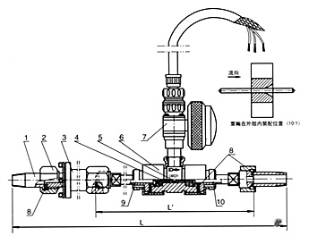
2, liquid flow direction when installation should be direction of arrow and indicating flow sensor shell, and the straight pipe upstream should be 6 or higher DS, downstream straight pipe should be 5 or more DS (DS for pipeline measured diameter) to be tested.
3, sensors should be far away from the external magnetic field, such as can't be avoided, necessary measures should be taken;
4, in order to not affect the normal delivery of the liquid, maintenance should be on both ends of the sensor installation outside the straight section of the bypass pipe ((as shown in figure 4); 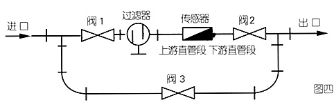
5, sensors, outdoor installation time, please prepare amplifier plug waterproof processing;
6, sensor and display instrument connection, should choose connection mode according to the power of the amplifier.
Ten, wiring and grounding considerations:
Wiring matters needing attention:
1, using a full cable as soon as possible.
2, should as far as possible away from electrical noise (such as power transformer, electric motor and the power cord), avoid parallel to the power the power cord wiring.
3, Suggestions in the end of the thick wire adopts the tin welding clamping lugs.
4, for the waterproof and mechanical damage, the cable into the metal tube inside, but may not have high power transmission cables, within the same catheter (a transmission cable transmission of zui power is greater than the flowmeter signal transmission cables z small power of 10 times, both cannot be installed on the same catheter).
5, the existing strong magnetic field outside the area, should make the axis of the detection device with the outside world vertical or the direction of the magnetic flux of the magnetic field with high permeability material for shielding flow sensor or external magnetic source.
6, explosion-proof type turbine flow sensor cable connection, must strictly abide by the relevant standards of explosion-proof amplifier.
Grounding problem:
1, the shielding wire can only be grounded at one end, on display instrument grounding.
2, reliable grounding should be good, explosion-proof type grounding resistance should be less than 10 Ω.
Ten, notable matters of installation:
1, before installation, pipeline purging, and in case of residual iron affect the normal operation of flowmeter.
2, before the installation, the use of tiny air blows the turbine, the turbine can flexible rotation, no random noise, count rotation is normal, uninterrupted card lag phenomenon, the flowmeter can be used to install.
3, in the middle of the flange and pipe flanges to add sealing washer.
4, before the gas meter shall be equipped with filters, temperament is dirtier occasions should add oil filter, before you place an order, can order to me at the same time, it is strictly prohibited to filter and flowmeter directly connected.
5, gas turbine flowmeter in the installation shall be added as of before and after the valve.
6, flange joint pipe Canon there should be no protrusions.
7, when installation, it is strictly prohibited in the import and export directly to where the flange welding, so as not to burn out flowmeter internal parts.
8, shall be installed in easy maintenance, strong electromagnetic interference and mechanical vibration and thermal radiation effects.
9, unfavorable use frequent interruptions in the flow, and have strong pulsation flow or pressure pulsation of the occasion.
10 and outdoor installation, should be the upper cover, to prevent rain water immersion and strong sunlight affect the service life of the meter.
11, can be horizontal or vertical installation, the fluid flow direction should be consistent with the direction of the logo on the shell, should guarantee the upstream of the flow meter is not less than 10 dn straight pipe, after the table is not less than 5 dn straight pipe.
12, in order not to affect the normal fluid transportation, it is suggested that according to the figure 2 by-pass pipe installation, must close the by-pass pipe valve when normal use.
Eleven, measurement range and working pressure:
1, ZW - LWGQ series gas turbine meter:
Nominal diameter | model | The standard range | Extended range | Stress levels | High pressure rating | installation |
DN20 | LWGQ-20 | 2.2-25 | 4-40 | 1.6 | 2.5, 4.0 | The flange |
DN25 | LWGQ-25 | 2.2-25 | 4-40 | 1.6 | 2.5, 4.0 | Flange (thread) |
DN32 | LWGQ-32 | 5-50 | 6-60 | 1.6 | 2.5, 4.0 | The flange |
DN40 | LWGQ-40 | 5-50 | 6-60 | 1.6 | 2.5, 4.0 | Flange (thread) |
DN50 | LWGQ-50 | 6-65 | 5-70. | 1.6 | 2.5, 4.0 | The flange |
LWGQ-50 | 10-100. | 8-100. | ||||
DN65 | LWGQ-65 | 15-200. | 10-200. | 1.6 | 2.5, 4.0 | The flange |
DN80 | LWGQ-80 | 13-250. | 10-160. | 1.6 | 2.5, 4.0 | The flange |
LWGQ-80 | 20-400. | The flange | ||||
DN100 | LWGQ-100 | 20-400. | 13-250. | 1.6 | 2.5 | The flange |
LWGQ-100 | 32-650. | The flange | ||||
DN125 | LWGQ-125 | 25-700. | 20-800. | 1.6 | 2.5 | The flange |
DN150 | LWGQ-150 | 32-650. | 80-1600. | 1.6 | 2.5 | The flange |
LWGQ-150 | 50-1000. | The flange | ||||
DN200 | LWGQ-200 | 80-1600. | 50-1000. | 1.6 | ... | The flange |
LWGQ-200 | 130-2500. | The flange | ||||
DN250 | LWGQ-250 | 130-2500. | 80-1600. | 1.6 | ... | The flange |
LWGQ-250 | 200-4000. | The flange | ||||
DN300 | LWQ-300 | 200-4000. | 130-2500. | 1.6 | ... | The flange |
320-6500. | 1.6 |
2Turbine flowmeter, ZW - LWGY series liquid:
Meter diameter(mm) | Normal flow range(m3/h) | Expand the flow range(m3/h) | Conventional resistance pressure(MPa) | Special stress levels(MPa) (Flange connection way) |
DN 4 | 0.04~0.25 | 0.04~0.4 | 6.3 | 12、16、25 |
DN 6 | 0.1~0.6 | 0.06~0.6 | 6.3 | 12、16、25 |
DN 10 | 0.2~1.2 | 0.15~1.5 | 6.3 | 12、16、25 |
DN 15 | 0.6~6 | 0.4~8 | 6.3、2.5 (The flange) | 4.0、6.3、12、16、25 |
DN 20 | 0.8~8 | 0.45~9 | 6.3、2.5 (The flange) | 4.0、6.3、12、16、25 |
DN 25 | 1~10 | 0.5~10 | 6.3、2.5 (The flange) | 4.0、6.3、12、16、25 |
DN 32 | 1.5~15 | 0.8~15 | 6.3、2.5 (The flange) | 4.0、6.3、12、16、25 |
DN 40 | 2~20 | 1~20 | 6.3、2.5 (The flange) | 4.0、6.3、12、16、25 |
DN 50 | 4~40 | 2~40 | 2.5 | 4.0、6.3、12、16、25 |
DN 65 | 7~70 | 4~70 | 2.5 | 4.0、6.3、12、16、25 |
DN 80 | 10~100 | 5~100 | 2.5 | 4.0、6.3、12、16、25 |
DN 100 | 20~200 | 10~200 | 2.5 | 4.0、6.3、12、16、25 |
DN 125 | 25~250 | 13~250 | 1.6 | 2.5、4.0 |
DN 150 | 30~300 | 15~300 | 1.6 | 2.5、4.0 |
DN 200 | 80~800 | 40~800 | 1.6 | 2.5、4.0 |
Twelve, selection of coding:
1, LWQ series gas turbine flowmeter selection:
type | ZW□□□ | - | - | - | - | Instructions (in the wei and control) | |||
LWQ-N | Basic three-wire system output pulse signal,+24VThe power supply | ||||||||
LWQ-A | Current output type4~20mAThe output,+24VThe power supply | ||||||||
LWQ-B | The display type3.6VBattery power | ||||||||
LWQ-C | The scene shows with4~20mAOr pulse output;+24VThe power supply | ||||||||
LWQ-D | Flow transmitter4~20mAThe output,+24VThe power supply.Temperature pressure compensation type | ||||||||
Nominal diameter | 20 | The normal flow The scope ofm3/h | 2.5-25 m3/h | Expand the flow The scope ofm3/h | 4-40 m3/h | ||||
25 | 2.5-25 m3/h | 4-40 m3/h | |||||||
32 | 5-50 m3/h | 6-60 m3/h | |||||||
40 | 5-50 m3/h | 6-60 m3/h | |||||||
50 | 6-65 m3/h | 5-70 m3/h | |||||||
65 | 15-200m3/h | 10-200m3/h | |||||||
80 | 13-250 m3/h | 10-160 m3/h | |||||||
100 | 20-400 m3/h | 13-250 m3/h | |||||||
125 | 25-700m3/h | 20-800 m3/h | |||||||
150 | 32-650 m3/h | 50-1000 m3/h | |||||||
200 | 80-1600 m3/h | 800-1600 m3/h | |||||||
250 | 130-2500 m3/h | 80-1600 m3/h | |||||||
300 | 200-4000 m3/h | 320-6500 m3/h | |||||||
explosion-proof | No mark for the explosion proof type | ||||||||
B | Explosion-proof type | ||||||||
Precision grade | A | precision1.0level | |||||||
B | precision1.5level | ||||||||
C | precision2.5level | ||||||||
The turbine type | A | Normal flow range | |||||||
B | Expand the flow range | ||||||||
2, LWGY series liquid turbine flowmeter selection:
type No. | said Ming wei tt&c) in ( | |||||||
ZW-LWGY | - | - | - | - | - | - | - | |
The male According to tong diameter | 4 | 4mm, the standard range0.04~0.25m3/h, wide range0.04~0.4m3/h | ||||||
6 | 6mm, the standard range0.1~0.6m3/hAnd quantity of wheel is wide0.06~0.6m3/h | |||||||
10 | 10mm, the standard range0.2~1.2m3/h, wide range0.15~1.5m3/h | |||||||
15 | 15mm, the standard range0.6~6m3/hWide range of0.4~8m3/h | |||||||
20 | 20mm, the standard range0.8~8m3/h, wide range0.4~8m3/h | |||||||
25 | 25mm, the standard range1~10m3/h, wide range0.5~10m3/h | |||||||
32 | 32mm, the standard range1.5~15m3/h, wide range0.8~15m3/h | |||||||
40 | 40mm, the standard range2~20m3/h, wide range1~20m3/h | |||||||
50 | 50mm, the standard range4~40m3/h, wide range2~40m3/h | |||||||
65 | 65mm, the standard range7~70m3/h, wide range4~70m3/h | |||||||
80 | 80mm, the standard range10~100m3/h, wide range5~100m3/h | |||||||
100 | 100mm, the standard range20~200m3/h, wide range10~200m3/h | |||||||
125 | 125mm, the standard range25~250m3/h, wide range13~250m3/h | |||||||
150 | 150mm, the standard range30~300m3/h, wide range15~300m3/h | |||||||
200 | 200mm, the standard range80~800m3/h, wide range40~800m3/h | |||||||
type | N | The sensor type:+12Vor24VPower supply, signal pulse output three wire system | ||||||
A | Transmitter type:+24VThe power supply, and two wire output4~20mA | |||||||
B | Intelligent: lithium-ion batteries, the scene show no signal output | |||||||
C | Intelligent:+24VPower supply, the scene display and output two wire4~20mA | |||||||
C1 | Intelligent:+24VDisplay with a power supply, the sceneRS486Communication protocol | |||||||
C2 | Intelligent:+24VDisplay with a power supply, the sceneHARTCommunication protocol | |||||||
Precision grade | 05 | precision0.5level | ||||||
10 | precision1.0level | |||||||
vortex wheel class type | W | Wide-range turbine | ||||||
S | Standard turbine | |||||||
material mass | S | 304Stainless steel | ||||||
L | 316(L)Stainless steel | |||||||
explosion-proof | E | Explosion-proof type (Explosion-proof level:ExdⅡBT6) | ||||||
Classes. | N | conventional | ||||||
H | High pressure | |||||||
13, the design and order guidelines:
1, you should pay attention to when ordering turbine flow sensor based on fluid nominal diameter (DN), work pressure (Mpa), temperature (℃), the flow range (m3 / h), fluid types and environmental conditions to choose the appropriate specifications.When have explosion-proof requirements must choose explosion-proof type sensor, and strict attention to explosive-proof grade.
2, need to jiangsu wei display instrument of form a complete set, please refer to the corresponding specifications, choose suitable model, or the information provided by our company technical personnel according to your designs for you selection.Indicate the specifications when you need to use the transmission signal cable length.
After-sales service commitment:
1, from the date of signing of the contract, I in the way provided for products of the company offers free maintenance and maintenance service, commitment to lifelong maintenance service;
2, jiangsu wei measurement and control instrument co., LTD. Sales manager will be in regular contact with customers, understand the usage of products, and solve the problems of the customers to use in the process of produce, free of charge to provide technical support;
3 the man-made damage is found, the warranty period, our company is responsible for the maintenance, and the resulting maintenance fee;
4, product quality problems or are not satisfied with product, the user can choose unconditional return, wei tt&c don't charge any fees, appear quality problem, bear the freight back and forth.
