

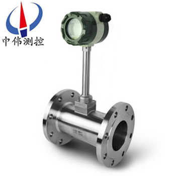
Liquid vortex flowmeter
Liquid vortex flowmeter is a kind of new flow meter has the international advanced level.Because it …
Description:
Products overview:
ZW - LUGB seriesLiquid vortex flowmeterIs using the liquid vibration principle and development of a new type of flowmeter, widely used in petroleum, chemical industry, metallurgy, paper and other fluid measurement.The flowmeter have no moving parts, high reliability, high precision, long life, can be in a very wide range of flow measuring precise instantaneous flow and cumulative flow of liquid.It is not affected by medium, the influence of temperature, pressure, viscosity and component without plugging, BuKa, not easy to scale formation, corrosion resistance, high temperature, high pressure safety explosion-proof, suitable for bad environment.Traffic integration of scoring display and remote transmission, and can output pulse signals or electric current signal and computer networking.
Second, the working principle:
ZW - LUGB seriesLiquid vortex flowmeter is by the design in the flow field in the vortex body, detection probe and the corresponding electronic circuit, etc.When the fluid flows through the spiral body occurs, it is formed on both sides of the two rows of vortex variations, this vortex is known as the karman vortex street.Stern, on the basis of the theory of karman vortex street Hal and puts forward the karman vortex street frequency is proportional to the velocity of the fluid, the relation between the frequency and velocity are presented:
F = St * V/d type:
F vortex frequency (Hz)
V vortex occurred body on both sides of the average flow velocity (m/s)
St, luo hall coefficient (constant)
These variations of vortex is formed a series of variations of negative pressure, the pressure on detecting probe, and produce a series of alternating electric signals, after dealing with the preamplifier conversion, plastic, amplification, the output is proportional to the vortex synchronous pulse frequency signal (or standard).
Applications:
ZW - LUGB seriesLiquid vortex flow meter according to the principle of Carmen (karman vortex street measuring gas volume flow of liquid, steam or, standard condition or volume flow to mass flow volume flow.Widely used in various industries of gas, liquid and steam flow measurement, can also be measured turbid liquid containing small makings, impurities, and can be used as flow transmitter used in automatic control system.
Four, the main features:
1, can measure the steam, gas, liquid and the volume flow to mass flow.
2, dismantling the can realize does not block the flow sensor, which can realize the amplifier and sensor separation (separation distance of 15 m).
3, USES the interference elimination circuit and anti vibration sensing head, make the instrument has certain environmental vibration resistance.
4, small pressure loss, wide range, range of 10 to 40 times.
5, no mechanical moving parts, long-term stability and simple structure is convenient for installation and maintenance.
6, measurable medium temperature up to + 350 ℃ (+ 450 ℃).
Five, the technical parameters:
Measuring medium: liquid, gas, natural gas, steam (saturated steam and superheated steam);
Measuring range: the Reynolds number is 5 x 10³ ~ 7 x 10⁶
Normal measuring range: Reynolds number is 2 x 10⁴ ~ 7 x 10⁶
Measuring velocity range: liquid 0.5 ~ 7 m/s gas 4 ~ 35 mm/s steam 7 ~ 70 m/s
By measurement of body temperature: - 40 ℃ ~ + 300 ℃
By measurement of body temperature: 1.6, 4, 25 mpa
Accuracy: level 1, 1.5, 0.5 (by nonlinear dressing can reach 0.5);
Repeatability: 0.2% of the indicated value;
The table body material: ICr18Ni9Ti;
Pressure loss: delta (r = 1.2 * 10-6 V2 type: delta r - P - pressure loss measured the fluid density (Kg/m3) v - tube average flow velocity (m/s) ambient temperature: - 20 ℃ ~ + 55 ℃ (special request order)
Environmental humidity: 90% RH or less
The atmospheric pressure: 86-106 kpa
External power source: 3.6 ~ 224 VDC
Power source: within 3 ~ 4.5 VVDDC
Working power supply: 80 / A
Operating voltage: 2.7 ~ 3.6 v
Operating frequency: 0.1 ~ 3000 h
Signal remote transmission distance: 100 mm
Signal output: pulse output (power source) 4 ~ 20 madc output current (two wire system for 24 VDC power supply) pulse output and the output current can only choose one way.
Six, appearance size:

DN | A | B | C | D |
15 | 90 | Φ 57 | 383 | 45 |
20 | 100 | Φ 57 | 388 | 50 |
25 | 100 | Φ 57 | 394 | 50 |
32 | 100 | Φ 65 | 396 | 50 |
40 | 100 | Φ 75 | 401 | 50 |
50 | 110 | Φ 87 | 407 | 55 |
65 | 110 | Φ 109 | 418 | 55 |
80 | 110 | Φ 120 | 423 | 55 |
100 | 120 | Φ 149 | 447 | 60 |
125 | 125 | Φ 175 | 474 | 65 |
150 | 145 | Φ 203 | 501 | 75 |
200 | 170 | Φ 259 | 556 | 100 |
250 | 190 | Φ 312 | 608 | 120 |
300 | 210 | Φ 363 | 660 | 140 |
350 | 230 | Φ 409 | 709 | 160 |
400 | 250 | Φ 460 | 756 | 180 |
450 | 275 | Φ 520 | 814 | 205 |
500 | 290 | Φ 575 | 869 | 225 |
Seven, pipe requirements:
1, the requirement for straight pipe:
In order to ensure that the instrument, accurate to run normally, sensor must have a certain straight pipe upstream and downstream of the installation points, to adjust the flow field, as shown.
Figure 1: concentric contraction tube;
Figure 2: the concentric expansion tube;
Figure 3: a 90 - degree Angle;
Figure 4: the same plane of two 90 - degree Angle;
Figure 5: different plane of two 90 - degree Angle;
Figure 6: regulating valve should be installed downstream of the sensor in 5 d to the distance, if the sensor must be installed in the upstream, the sensors should be not less than 50 d upstream, straight pipe section downstream straight pipe section should be not less than 5 d.
2, the requirement of pipe:
A, upstream and downstream piping diameter D and the same as the sensor inner diameter DN, its difference satisfy the following conditions: 0.95 DN D 1.1 or less or less DN.
B, piping shall be concentric with sensor, coaxial degree should be less than 0.05 DN.
C, gasket not protruding into the pipe, the inner diameter slightly larger than sensors.
D, if you want to stop inspection and cleaning the sensor, the by-pass pipe should be set up,As shown in the figure below.

3, the requirement of pipe vibration:
Sensors to avoid installed on the strong pipeline vibration, if necessary to install, shock absorption measures must be taken, respectively at the upstream and downstream of sensor 2 d piping fastening device, and vibration-proof pad.
Special note: in the air compressor exit strong vibration, cannot install the sensors, shall be installed after the gas storage.
4, demand for air condition:
A, the gas to be tested for single phase pipe flow, continuously flowing through a pipe.
Before b, the gas flows through the flowmeter, the flow rate must be parallel to the pipe axis, can not have vortex flow.
C, flow should be a subsonic, a pulse, its flow change slowly over time.
5, the flowmeter installation requirements:
Vortex street flowmeter to process the installation and use of the special requirements of environment is not too much, but any kind of flow measurement instrument has such a common, as far as possible to avoid vibration and high temperature environment as flow interference elements (such as compressor, separator, pressure regulating valve, reducer, and pipe, elbow, etc.), keep straight pipe before and after the instrument inside sleek straight, ensure to clean single-phase fluid measured medium, etc.
Eight, installation requirements:
1, the sensor can be installed indoors, can also be installed in the outdoor.Environmental conditions to conform to the requirements.
2, sensors should be installed in a horizontal, vertical or inclined (fluid flow from bottom to top) and its corresponding pipe nominal diameter.
3, sensors installed on a mechanical vibration of pipeline should be avoided.Should be considered when the vibration is inevitable, at about 2 dn from sensor before and after the straight pipe and fixing racks.
4, avoid install the sensor sensing has strong electromagnetic interference, thermal radiation, corrosive gas, the space is little, and maintenance is not convenient.
5, when measured medium contains many impurities, at the request of straight pipe upstream from sensors mounted outside the length of the filter.
6, either upstream or downstream of the sensor should be configured with a certain length of straight pipe, straight pipe inner surface should be clean, smooth, no obvious convex concave, fouling and peeling phenomenon.Its length should conform to the requirements of figure 2.Installation of the liquid sensor, near the pipe should be filled with liquid to be tested.
7, straight pipe diameter as far as possible consistent with the sensor size, if not consistent, slightly larger diameter than the sensor size should be adopted, the error to 3% or less is not more than 5 mm.
Nine, note:
1, special flange and straight pipe welding can't with the sensor.
2, when installation should make the flow of sensor mark the direction of flow and the pipe.
3, before the installation of sensor and the flange must be put away in sealing ring grooves.The location of the pressure and temperature measurement point, pressure downstream of the sensor in 3 ~ 5 dn, temperature measuring points in the downstream of 5 ~ 8 dn.
4, when measuring high temperature medium, do not use heat insulation material to wrap around the sensor link rod.
Five, connection of shielded cable, should as far as possible away from the interference of strong electromagnetic field.Absolutely not allowed with high voltage cable laying, shielded cable to shorten as far as possible, and shall not be volume, in order to reduce stray inductance, zui big length should be not more than 200 meters.
6, before installation of sensors, pipeline cleaning must be conducted.Flow after rinse tube impurities, avoid clogging sensor.Measuring liquid pipe must be full of measured liquid, prevent the interference of bubbles.
7, measuring gas pipelines to prevent the interference of reservoir fluid.Installation position as shown in figure 5.Replace the probe body under the high temperature and high pressure, it must be safe operation, high temperature protection.After cooling step-down replaceable probe at the bottom of the safety conditions.
Ten, installation specification management:
Vortex street flowmeter standard installation, to use the department in the subsequent management provide strong technical support, put forward the following specific requirements of the construction unit, after years of validation effect is very good.
1, with 4 ~ 20 ma output, pulse output.
2, GPRS remote transmission device with pulse input, input 4 ~ 20 ma.
3, with power supply prevents thunder and lightning protection (4 ~ 20 ma) signal.
4, instrument cabinets for: ark with UPS power supply, open and the socket, the GPRS communication devices, intelligent vortex flowmeter converter such as concentrated installation and lock.
5, smooth instrument ark need concrete pier base, instrument protection grade for outdoor cabinet, the ark with insulating layer to prevent sun point-blank, ark with water proof function.
6, domestic demand has left side table well enough straight pipe, facilitate intelligent vortex flowmeter test, compare and follow-up management.
7, the design of intelligent vortex flow timing front must have at least 10 times of nominal menstruation (dn) 10 straight pipe, the back-end must leave more than 5 dn straight pipe, to ensure accurate measurement.
8, shall be installed in accordance with the specifications and after the installation need measuring grounding, grounding resistance should be under 10 Ω.Equipotential connections using multiple strands of copper wires, cables should be greater than or equal to 16 was;Instrument grounding line using multiple strands of copper conductor, cable requirement was greater than or equal to 6.Grounding standard see GB50343-2009 "technical specification for building electronic information system lightning protection.
Eleven, standard of flow range profile: unit (m3 / h)
traffic | The liquid flow range | Gas flow range | Saturated steam flow range | |||
CAL | Small flow | Heavy traffic | Small flow | Heavy traffic | Small flow | Heavy traffic |
DN25 | 0.9 | 14 | 8.3 | 110 | 13 | 1500 |
DN40 | 2.5 | 35 | 26 | 300 | 25 | 4400 |
DN50 | 3.3 | 55 | 36 | 480 | 40 | 6800 |
DN80 | 8 | 150 | 90 | 1300 | 100 | 19000 |
DN100 | 14 | 240 | 140 | 2000 | 160 | 29000 |
DN150 | 38 | 450 | 290 | 4100 | 350 | 66000 |
DN200 | 70 | 850 | 620 | 7500 | 620 | 118000 |
DN250 | 130 | 1300 | 700 | 12500 | 970 | 185000 |
DN300 | 180 | 2000 | 920 | 16500 | 1400 | 267000 |
Twelve, selection of coding:
Code name | size | Flow range ㎡/h(In the wei and control) | ||||
ZW-LUGB-25 | DN25 | 1 ~ 10(liquid) | 25 ~ 60(gas) | Steam flow check specifications,DN300The above recommended plug-in vortex flowmeter | ||
ZW-LUGB-32 | DN32 | 1.5 ~ 18(liquid) | 15-150(gas) | |||
ZW-LUGB-40 | DN40 | 2.2 ~ 27(liquid) | 22.6 ~ 150(gas) | |||
ZW-LUGB-50 | DN50 | 4 ~ 55(liquid) | 35 ~ 350(gas) | |||
ZW-LUGB-80 | DN80 | 9 ~ 135(liquid) | 90 ~ 900(gas) | |||
ZW-LUGB-100 | DN100 | 14 ~ 200(liquid) | 140 ~ 1400(gas) | |||
ZW-LUGB-150 | DN150 | 32 ~ 480(liquid) | 300 ~ 3000(gas) | |||
ZW-LUGB-200 | DN200 | 56-800(liquid) | 550 ~ 5500(gas) | |||
Code name | function1 | |||||
N | No temperature pressure compensation | |||||
Y | With temperature compensation | |||||
Code name | Output type | |||||
F1 | 4-20mAOutput (two-wire system) | |||||
F2 | 4-20mAOutput (three-wire system) | |||||
F3 | RS485Communication interface | |||||
Code name | Measured medium | |||||
J1 | liquid | |||||
J2 | gas | |||||
J3 | steam | |||||
Code name | The connection method | |||||
L1 | Flange mounted | |||||
L2 | Flange connection type | |||||
Code name | function2 | |||||
E1 | 1.0level | |||||
E2 | 1.5level | |||||
T1 | The normal temperature | |||||
T2 | The high temperature | |||||
T3 | steam | |||||
P1 | 1.6MPa | |||||
P2 | 2.5MPa | |||||
P3 | 4.0MPa | |||||
W1 | internal3.6VThe power supply | |||||
W2 | DC24VThe power supply | |||||
N1 | Stainless steel | |||||
N2 | Carbon steel | |||||
N3 | Anti-corrosion type | |||||
Thirteen,Order to choose selection guidelines:
Name and model number of 1, 1), (2) the diameter, flow range, (3) whether or not to bring the attached so that we can correct selection for you, (4) using pressure, (5) the use of medium temperature.
2, if has been selected by design units in the way of vortex street flowmeter types, please press type vortex flowmeter directly order from our sales department.
3, when using occasions is very important, or the environment is complex, please try to provide the design drawings and detailed parameters, by wei experts in our audit checks for you.
After-sales service commitment:
1, from the date of signing of the contract, I in the way provided for products of the company offers free maintenance and maintenance service, commitment to lifelong maintenance service;
2, jiangsu wei measurement and control instrument co., LTD. Sales manager will be in regular contact with customers, understand the usage of products, and solve the problems of the customers to use in the process of produce, free of charge to provide technical support;
3 the man-made damage is found, the warranty period, our company is responsible for the maintenance, and the resulting maintenance fee;
4, product quality problems or are not satisfied with product, the user can choose unconditional return, wei tt&c don't charge any fees, appear quality problem, bear the freight back and forth.
Browse:
