

Products overview:
ZW - LDE series intelligent electromagnetic flowmeter is a kind of measuring tube according to Faraday's law of electromagnetic induction induction of conductive medium volume flow meter, using the world's advanced technology.Using the constant current low-frequency rectangular wave three values or double frequency rectangular wave excitation, the advantages of both the rectangular wave magnetic field, and overcomes the drawback of sinusoidal magnetic field;Can also eliminate the power supply voltage fluctuation, power frequency and the excitation coil impedance changes caused by the error;And has excellent stability of zero point and is not affected by fluid noise interference.Which has the characteristics of high stability, high reliability.Electromagnetic flowmeter is composed of sensors and switches, sensors installed on the measuring pipe, the converter can be connected to the sensor combination together referred to as electromagnetic flowmeter, a size converter is installed within 100 meters of within 30 meters away from the sensor or occasions, are connected by a shielded cable is called separation between type electromagnetic flow meter.Is the main component of the electromagnetic flowmeter sensor: measuring tube, electrode, excitation coil, magnetic yoke iron core and shell.
Second, the working principle:
ZW - LDE seriesIntelligent electromagnetic flowmeter based on Faraday electromagnetic induction principle, with the sounding pipe axis and the magnetic field lines in the vertical tube wall installed on a pair of detecting electrodes, when conducting liquid along the measuring tube axis movement, conductive liquid cutting lines of magnetic force induced electric potential, the induction electric potential by two detection electrodes detection, numerical size and flow into a direct ratio, its value is: E = KBVD type:
E - induction electric potential;
K - factor related to the magnetic field distribution and the axial length;
B - magnetic induction intensity;
V - conductive liquid average flow velocity;
D - electrode gap;(the measuring tube diameter)
Sensor will be induced potential E as traffic signal, sent to the converter, amplifying, transform filter with a series of digital processing, USES dot matrix LCD display with backlight instantaneous flow and cumulative flow.Converter has 4 ~ 20 ma output, alarm output and frequency output, and is equipped with RS - 485 communication interface, and supports HART and MODBUS protocol.
Applications:
ZW - LDE seriesIntelligent electromagnetic flowmeter is mainly used to measure volume flow of conducting liquid and slurry in the closed pipeline.Such as water, sewage, slurry, pulp, all kinds of acid, alkali, salt solution, food slurry, etc., widely used in petroleum, chemical, metallurgical, textile, food, pharmaceutical, paper making industries and environmental protection, municipal administration, water conservancy construction and other fields.
Four, the structure form:
1, the sensor:
Sensor is mainly composed of measuring tube and electrode, excitation coils, iron core, magnetic yoke and shell.
A, measuring catheter: by stainless steel tube, the lining and the connecting flange, as the carrier of measured liquid measurement working conditions on site.
B, measuring electrode: installed in the measuring tube inside wall, and the axial direction perpendicular to a pair of electrodes to measure liquid signal generation.
: c, excitation coil in a magnetic field measurement of intraductal two excitation coil.
D, iron core and magnetic yoke: the excitation coil of the magnetic field generated import liquid, and the magnetic circuit.
E, shell: instrument packaging.
2, the converter:
Is the smart secondary table, it will flow signal amplification processing stymied microcontroller after operation, can display flow, total amount, and can output pulse and analog current signal, used in the measurement or control of fluid flow.
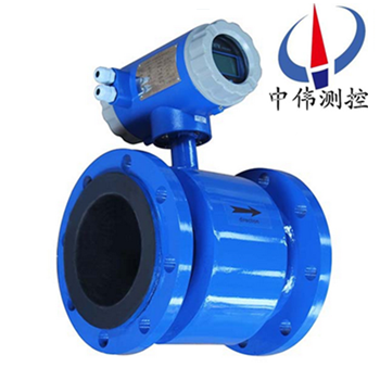
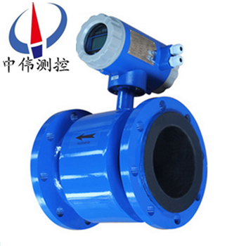
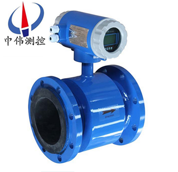
3, product assembly form:
It into a shape and size in two forms.
A, a shape: mounted sensors and switches.
B, size: separation installation sensor and converter, through the connecting cable form flow metering system.
C, in order to adapt to the measurement demands of the different medium, the lining of sensor and electrode materials can have many choices.
Five, the main features:
1, instrument structure is simple, reliable, have no moving parts, working life is long;
2, no closure choke parts, there is no loss of pressure and fluid blocking phenomenon;
3, no mechanical inertia, fast response and good stability, can be applied to automatic testing, adjusting and SPC system;
4, the measurement precision is not affected by the type of measured medium and its temperature, viscosity, density, the influence of physical parameters such as pressure;
5, adopt ptfe or rubber lining material and Hc, Hb, 316 l, the different combination of electrode materials such as Ti can meet the needs of the different media;
6, with pipeline, plug-in, such as a variety of flow meter type;
Block 7, using EEPROM memory, measuring operation safe and reliable data storage protection;
8, integration and separation of two types;
9, high-definition LCD backlit display.
Vi.Technical parameters:
1, precision instrument: pipeline magnitude 0.5, 1.0;Plug in 2.5 on the Richter scale are unlikely.
2, measuring medium: conductivity is greater than 5 mu S/cm of various liquid and liquid-solid two-phase fluid.
3, velocity range: 0.2 ~ 8 m/s.
4, work pressure: 1.6 MPa.
5, environmental temperature: - 40 ℃ ~ + 50 ℃.
6, medium temperature: ptfe lining 180 ℃ or less;Rubber lining material 65 ℃ or less.
7, explosion-proof marks: Exmibd Ⅱ BT4.
8, explosion-proof number: GYB01349.
9, outside magnetic interference: 400 a/m or less.
10, shell protection: integration type: IP65;
In mold: sensor IP68 (5 meters underwater, rubber lining only);Converter IP65.
11, the output signal: 4 ~ 20 ma DC, load resistance Ω 0 ~ 750.
12, communication output: RS485 and CAN bus.
13, electrical connections: M20 x 1.5 internal thread, phi 10 cable hole.
14, power supply voltage: 90 ~ 220 v AC, 24 + / - 10% V.D C.
15, zui big power consumption: 10 or less va.
Seven,Installation requirements:
The choice of installation environment
1, should as far as possible away from strong electromagnetic field equipment.Such as big motor, transformer, etc.
2, the installation place should not have a strong vibration, environmental temperature change is not big.
3, easy to install and maintenance.
The choice of the installation position
1, sensors, flow mark on the direction of the measured medium flow and the pipe must be consistent.
2, installation location must ensure that the measuring tube in the book is full of measured medium.
3, and the choice of fluid flow pulse smaller places, which should be far away from the pump and local resistance (valve, elbow, etc.)
4, the measurement of two-phase fluid, should choose is not easy to cause the location of the phase separation.
A negative pressure, avoid installed in a tube of five places.
6, when makes the electrode measured medium, measure the tube inner surface adhesion, scaling, suggest the measuring tube flow velocity of no less than 2 m/s.
At this time can use reducing pipe diameter slightly smaller than the process.For uninterrupted flow in the process piping cleaning electrode and the measuring tube, sensor can be used parallel installations, and cleaning.
The choice of the installation site
In order to make the transmitter work stability, when choosing the location should be paid attention to the following requirements:
1, try to avoid strong ferromagnetic objects and concrete equipment of electromagnetic field (such as a big motor, transformer, etc.), so as to avoid the magnetic field of magnetic field effect sensor and traffic information.
2, should be installed in a dry and ventilated place, should not be in damp, easy seeper place of installation.
3, should try to avoid weathered, avoid environmental temperature is higher than 45 ℃ and relative humidity is more than 95.9%.
4, choose to facilitate maintenance and convenient place.
5, flow meter should be installed in the pump back end, never on the suction side of the installation;Valve should be installed in the downstream flow meters.
Eight, main advantages and disadvantages are as follows:
Main advantages are as follows:
1, the flow sensor structure is simple, the measuring tube has no moving parts, no obstacles to fluid flow throttling components.So when the fluid flow through timing does not cause any additional pressure loss, flow meter is running in one of the flowmeters zui low energy consumption.
2, measurable smudges medium, corrosive medium and clouding the liquid-solid two phase flow of traffic.This is due to internal unimpeded flow meter tube parts, and the measurement of body contact is sounding pipe lining and electrode, the materials can choose according to the nature of the current body.For example, made from poly three fluoride or ptfe lining, can measure all kinds of acid, alkali, salt and other corrosive medium.Adopt wear-resisting rubber lining, is especially suitable for measuring with solid particle slurry, water slurry, wear a large liquid-solid two phase flow and various liquid with fiber and pulp suspension.
3, is a kind of volume flow measuring instrument, in the process of measurement, it is not affected by the temperature of the measured medium, viscosity and density with conductivity (in a certain range.Therefore, electromagnetic flowmeter only after water calibration, it can used to measure the conductivity of liquid flow.
4, the output of the meter only is proportional to the average flow velocity of the measured medium, and under the symmetric distribution of flow state (laminar flow and turbulent flow).So the electromagnetic flowmeter range very wide range, the measurement range can be up to 100:1, some even up to 1000:1 working flow range.
5, no mechanical inertia, responsive, can measure the instantaneous pulse flow, also can measure the rate of flow of positive and negative two directions.
6, industrial use very wide range of the calibre of the electromagnetic flowmeter, from a few millimeters to a few meters, and the domestic existing diameter up to 3 m's real flow calibration equipment, which laid a foundation for the application and development of electromagnetic flow meter.
There is still the main deficiencies.
1, cannot be used for measuring gas, steam and liquid contains a lot of gas.
2, low cannot be used to measure the conductivity of liquid medium, such as the petroleum products or organic solvent such as medium, the electromagnetic flowmeter is powerless.
3, due to the measuring tube lined with the limitation of materials and electrical insulation materials, can not be used in measuring high temperature medium;If without special treatment, also cannot be used for the measurement of low temperature medium, in order to prevent the measuring tube condensation (frost) destruction of insulation.
4 the influence of electromagnetic interference, vulnerable to the outside world.
Nine, troubleshooting:
Due to all kinds of faults in the operation of flowmeter in can cause measurement is allowed to occur, generally in the electromagnetic flow meter of faults in the operation probably can be divided into two classes.Kind of fault for flow meter itself, component damage caused by fault;The change caused by the fault for external conditions, such as the output flow instability, countless times, large error and so on.Here are some simple troubleshooting way:
A, the instability of the output: 1. The unstable flow field;2. Through the sensor of the gas in the liquid, solid block;3. The electrical connection in the empty pick up;4. Bad earth;5. The electrode leakage solution: 1. The transformation pipeline, or increase the false sensor installation;2. Normal phenomenon;3. Check the wiring, then good line;4. Good earthed;5. Repair sensors.
B, no liquid output: 1. Between the converter and signal transmission cable conductor by the two;2. Power did not pick up or poor contact;3. The sensor instrument piping, shell, end face has a leakage.Solution: 1. The thread;2. Connect the power supply, for maintain good contact;3. Repair sensors.
C, liquid flows have not output: 1. Between the converter and signal transmission cable connection circuit;2. Signal cable to the electrode connection circuit;3. The electrode surface contamination or sedimentary insulating layer;4. Bad earth or open circuit.The solution: 1. Connect the cable for;2. Open the sensor, in again;3. Wash electrode surface;4. Good earthed.
Too much d, error: 1. The zero point is too high;2. Not completely filled with liquid.3. Power supply distortion is too large;4. Bad earth.The solution: 1. To adjust the zero point;2. Improve the conditions of pipeline, sensor is always full of liquid.(3) improve the power supply condition, conform to the normal working conditions;4. Good earthed.
The preparing work before ten, run:
1, put into operation after installation wiring should be checked again before the installation, wiring is correct.(the size)
2, before the bed bottom valve is opened, the sensor after the valve closed, let the sensor with the medium.
3, after the completion of the preparation, upstream of the valve to open the first sensor, then slowly open the downstream of the valve, observe the converter instantaneous flow display should be toward the direction of change, that signal lines in the right direction.Otherwise, will signal A and B connection swap position.(the size)
4, open the sensor before and after the valve, drainage for a few minutes, the gas discharge tube.
5, close the sensor downstream of the valve, then close upstream of the valve, the measured medium is inside the sensor.And then to form a complete set of adjustment.Sensor and converter matching coefficient of zero adjustment and instrument set converter specifications, please read them.
11 and the matters needing attention during installation.
1, the axis of the measuring electrode must be similar to horizontal direction;
2, measuring the pipe must be completely filled with liquid.
3, less flowmeter zui ahead to have 5 * D for flow meter diameter (D) the length of the straight pipe, the rear zui to have less 3 * D for flow meter diameter (D) the length of the straight pipe;
4, the direction of fluid flow and the direction of arrow flowmeter;
Five should have can be damaged by vacuum meter, the pipe lining, special attention should be paid;
6, near the flow meter should be no strong electromagnetic field;
7, shall have plenty of space, near the flowmeter to installation and maintenance;
8, if measuring pipeline vibration, the flowmeter should be fixed on both sides of bearing when measuring the mixed liquid of different medium hybrid point and the distance between the flowmeter zui to have less 30 x D for flow meter diameter (D) the length of the cleaning and maintenance for the convenience of the flowmeter, should install bypass pipe.
Twelve, grounding protection, must pay attention to the following:
1, sensor, converter should be separate grounding, never even on the motor, process piping, grounding resistance should be less than 10 ohms.
2, sensor measurement of tube and shell, shielded wire, converter and secondary instrument must be grounded.
3, sensors, converters, grounding on the scene, to the shield in the control room side of the secondary instrument grounding, not multiterminal grounding, lest introduced due to different potential interference.
4, sensors installed in a metal tube, the sensor can be grounding wire connected to the pipe flange according to the requirement of the factory, the formation of reliable grounding instrument ground should be an independent site, can not share other electrical equipment grounding.
13, the main technical data:
1, the whole machine and the technology of sensor data:
Execution standard | JB/T 9248—1999 | ||||
Nominal diameter | 15, 20, 25, 32, 40, 50, 65, 80, 100, 125, 150, 200, 250, 300, 350, 400, 450, 500, 600, 700, 800, 900, 1000, 1200, 1400, 1600, 1800, 2000, 2200, 2400, 2600, 2800, 3000 | ||||
High velocity | 15m/s | ||||
precision | DNl5~DN600 | Show the value of the: plus or minus 0.3% (velocity of 1 m/s or higher);Plus or minus 3 mm/s < 1 m/s (velocity) | |||
DN700—DN3000 | Plus or minus 0.5% of the value (velocity of 0.8 m/S or higher);Plus or minus 4 mm/s < 0.8 m/s (velocity) | ||||
Fluid conductivity | ≥5uS/cm | ||||
Nominal pressure | 4.0MPa | 1.6MPa | 1.0MPa | 0.6MPa | 6.3、10MPa |
DNl5~DN150 | DNl5~DN600 | DN200~DN1000 | DN700~DN3000 | Special orders | |
The environment temperature | The sensor | - 25 ℃ - 10 to 60 ℃ | |||
Converter and a body | - 10 ℃ - 10 to 60 ℃ | ||||
The lining material | Ptfe, chloroprene rubber, polyurethane, fep (F46), and network PFA | ||||
High fluid temperature | - size | 70 ℃ | |||
The separation type | Poly (chloroprene rubber lining | 80 ℃;120 ℃ (when ordering specify) | |||
Polyurethane lining | 80 ℃ | ||||
Ptfe lining | 100 ℃;150 ℃ (when ordering specify) | ||||
Fep (F46) | |||||
And network PFA | |||||
Signal electrode and the grounding electrode materials | Stainless steel 0 crl8nil2m02ti B, C, hartz hartz alloy alloy, titanium, tantalum, platinum/iridium alloy, stainless steel coated with tungsten carbide | ||||
Electrode institutions | DN300—DN3000 | ||||
Connecting flange material | Carbon steel | ||||
Grounding the flange material | Stainless steel 1 crl8ni9ti | ||||
Import protection flange material | DN65—DNl50 | Stainless steel 1 crl8ni9ti | |||
DN200~DNl600 | Carbon steel stainless steel 10 1 crl8ni9ti | ||||
Enclosure protection | DNl5 ~ DN3000 separation type rubber or polyurethane lining sensor | IP65 or IP68 | |||
Other sensors, bodily form separated type flowmeter and converter | IP65 | ||||
Spacing (separation type) | Converter distance sensor is generally not more than 100 m | ||||
